At Embedded World I gave a talk on embedded security. There was also an associated paper, and I’m now making those available. I’ve also duplicated the paper contents in this blog post for your ease of access.
Download Slides (PPTX):

ABSTRACT: As interconnected devices proliferate, security of those devices becomes more important. Two critical attacks can bypass many standard security mechanisms. These attacks are broadly known as side-channel attacks & fault injection attacks. This paper will introduce side-channel power analysis and fault injection attacks and their relevance to embedded systems. Examples of attacks are given, along with a short discussion of countermeasures and effectiveness. The use of open-source tools is highlighted, allowing the reader the chance to better understand these attacks with hands-on examples.
Introduction
Side-channel attacks are the broad class given to attacks which rely on “additional information” that is accidentally leaked. A variety of such side-channels exist, such as the time an algorithm takes to execute can betray information about the code paths taken in the algorithm. Of great interest to embedded developers is side channel power analysis, first introduced by Kocher et al. in 1999 [1]. This attack takes advantage of a small piece of information – the data being processed by a system affects the power consumption of that system. This allows us to break advanced cryptography systems such as recovering an AES-256 key in a matter of minutes. These attacks do not rely on substantial resources – they can be performed with commodity hardware and for less than $50. A second class of attack will be known as fault injection attacks. They allow us to modify the program flow of code, which can cause a variety of security flaws to be exploited. This paper will briefly introduce those two methods of attacks and discuss how engineers can understand them to develop effective countermeasures.
Power Analysis for Algorithm Flow
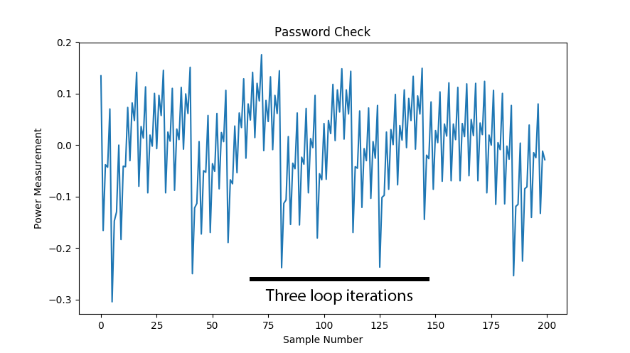
The most basic form of power analysis attack is simple power analysis. In this method we will extract information about the algorithm flow. This could be used to directly extract key bits where changes in program flows reveal key information (such as with RSA), but can also be used to extract information such as timing that simplifies further attacks. Observe a simple password check which checks a byte of the password at a time. The execution time through this algorithm would reveal which password byte was incorrect, allowing an attacker the ability to quickly brute-force the algorithm. A password of ADBC would entail only the guess sequence “A/A..B..C..D/A..B../A..B…C” to find the correct password, as once the correct letter is found for one digit the guess algorithm can move onto the next digit.
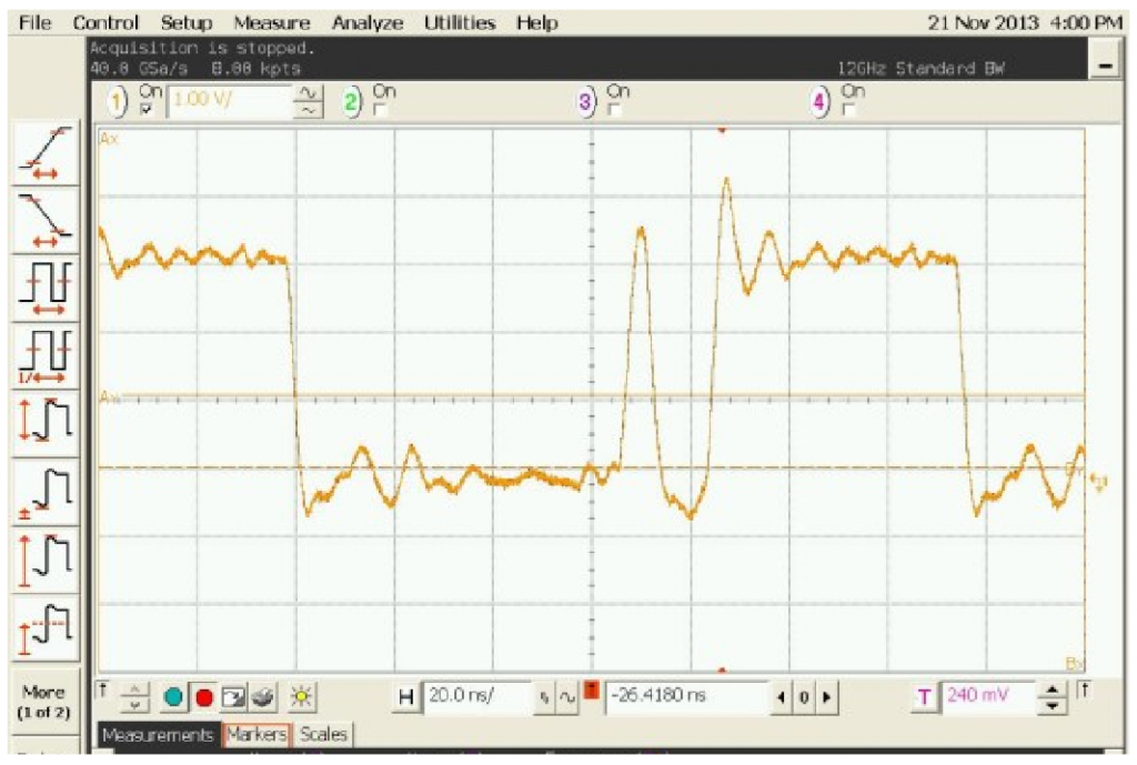
Such an attack could be performed from the communications protocol. But many systems will add a random delay before returning the results. With power analysis we could see the unique signatures in the power trace, as in Figure 1. Fig. 1. A simple password check shows how many iterations through the loop we took.
These power measurement examples are taken with the ChipWhisperer project. Here the power measurements are done by inserting a shunt resistor into the device power pin, and using the fact that a change in current will cause a change in voltage across the resistor. The decoupling capacitors are removed in this example to provide a clean signal. This is shown in Figure 2.

Note that using an EM probe could also provide a useful signal. An EM probe takes advantage of the fact a changing current through the device generates a changing EM signature, allowing the power analysis to succeed without requiring changes to the circuit board.
Power Analysis for Data Extraction
Besides understanding program flow, we can also directly extract data on internal busses. This allows recovery of keying material for algorithms such as AES-128. This works by taking advantage of the fact that changing the internal data bus is equivalent to charging or discharging a capacitor. Setting two data bits on the bus to ‘1’ takes more power than setting one data bit on the bus to ‘1’. This is not just a theoretical consideration – Figure 3 shows the power usage of a device processing data with differing Hamming weights (HW). These measurements were performed on a real hardware platform (ChipWhiperer-Lite), and is something you can easily confirm yourself.
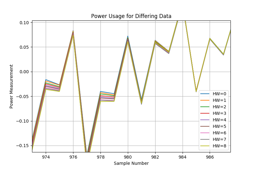
Figure 3: Showing Multiple Hamming Weights
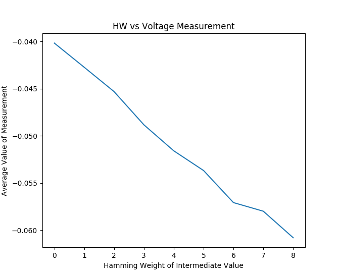
We don’t even claim to need knowledge of the exact Hamming weight. We look for just the linear relationship between a Hamming weight and the power consumption, as you can see in Figure 4 where I’ve plotted the value of sample point 978 for various Hamming weights. Note that there is a very strong linear relationship, and this linear relationship exists only when the correct data-point was chosen.
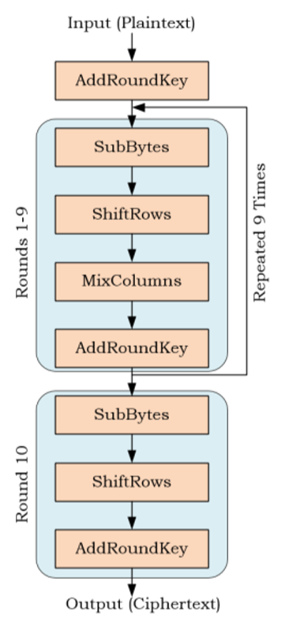
How does this help us break cryptography? Consider the full AES algorithm, shown in Figure 5. A byte of the secret key is XOR’d with a byte of the input data (AddRoundKey operation), and passed through a substitution box (SubBytes operation). This is repeated for each of the successive bytes. Note that despite the large key size of AES, this operation occurs a single byte at a time. We can take advantage of the correlation between the Hamming weight at the output of the S-Box and power usage of the device by trying to find this linear relationship in the power trace.
Rather than having known data and plotting it to find the exact location of this linear relationship, we look for any point in the power trace showing that linear relationship. The only way this linear relationship would exist is if our data was the actual data processed on the hardware – that means both the secret key and input data we use to calculate the Hamming weights are the actual ones processed by the device. Since we could assume we know the input data, we have to only perform a guess of a single byte at a time of the secret key. This allows recovery of the secret key in a very short period of time, assuming no protections are present on the device.
Fault Injection Attacks
Fault injection attacks allow one to bypass security mechanisms. The most basic example would be to consider an authentication check. If one could bypass that check, there would be no need to break the cryptography at all. This would allows us to trick the system into loading the incorrect data, as the signature verification step is completely ignored. Fault injection typically allows us to achieve this. There are many ways of performing it, the most common are clock glitching, voltage glitching, and electromagnetic fault injection (EMFI). Clock glitching relies on inserting very narrow clock edges near the “actual” clock edge (see Figure 6). These clock edges cause setup & hold times to be violated internally, which allows incorrect data to be propagated through the system. The exact effect varies based on timing, but for example this could cause an instruction load to be skipped, an instruction to be changed into another instruction, incorrect data to be saved, or register flags to not be written. Voltage glitching inserts waveforms into the power supply of the target. These could be generated using very simple methods, such as shorting the power pins together for very short periods of times (nS to uS). More complex faults could be achieved using a waveform generator and amplifier for example, or an analog multiplexor to switch between two or more voltage levels.
Finally electromagnetic glitching uses a strong current introduced into a coil near the target device. This causes voltages to be induced in the target device, and can cause similar effects to the previous fault injection methods. In addition, this can corrupt directly SRAM data, and not just change the state of dynamic data in-flight.
EMFI Through the Enclosure
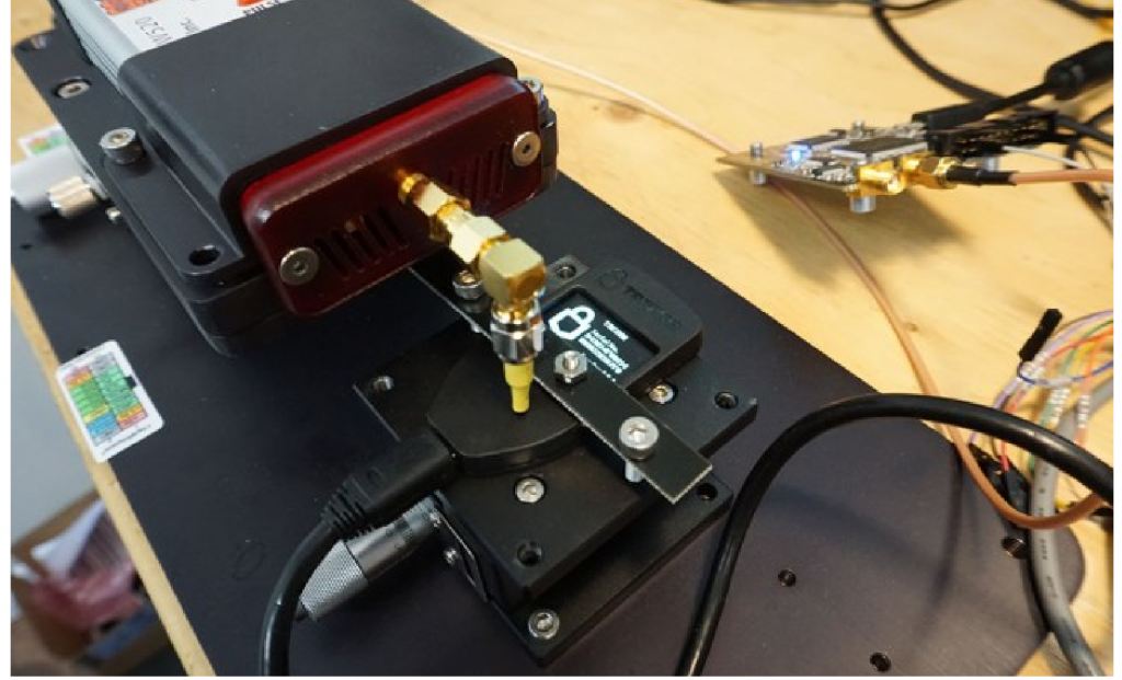
An interesting application of EMFI is that it can be performed through the enclosure of the device. Consider the Trezor bitcoin wallet for example. It contains a STM32F205 microcontroller located ~1mm below the surface of the device. This allows EMFI to target the device without opening the enclosure, as in Figure 7. One critical piece of information stored inside the flash memory of this chip is the “recovery seed”, and knowledge of that seed would allow someone to recover the data stored within it.
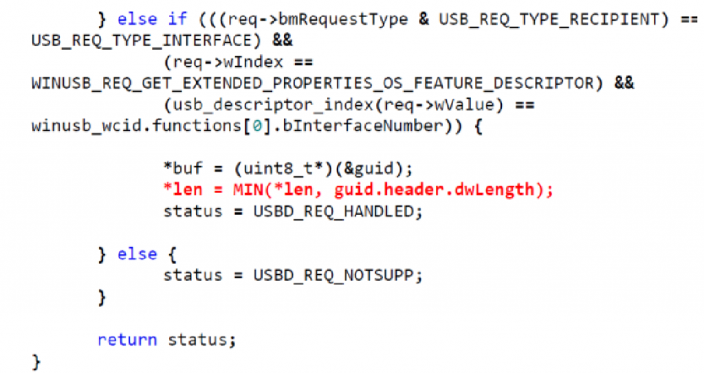
We can use FI to cause the data to be returned to us on demand. This takes advantage of the implementation of how a USB control read is performed for reading some of the USB descriptors. The critical section of the code is shown in Figure 8. A user requests a specific descriptor, and as part of the USB standard the user requests an expect number of bytes. The USB stack then returns up to requested number of bytes, but can return less if the requested data structure is smaller. The data structure in question for this code is 146 bytes, but we could freely request up to 0xFFFF bytes. The Trezor will not return 0xFFFF bytes as the data structure is only 146 bytes, so no exploit exists. But we can use FI to inject a fault at the moment the length comparison is done, and cause the wallet to return the full 0xFFFF bytes. In this case critical security data lies in flash memory after the descriptors, allowing us to easily read out this critical data.
The location of the fault injection requires some search and a degree of luck. The processing of the USB command is not time-definite due to jitter resulting from the queue. But the result of this is that a single successful glitch can cause a successful dump of the recovery information. A low success rate is meaningless if we can perform thousands of tries relatively quickly, as is the case for this specific device.
Countermeasures and Secure Design
A variety of techniques are available to reduce the impact of the attacks outlined here. Blindly applying the techniques is insufficient to guarantee successful countermeasures, as many platform and device specific implementation details can impact their effectiveness. The first step in developing secure systems must be to understand how the attacks work, so you can validate countermeasures.
Instrumentation Setup
Setup of an instrumented environment is the first step in applying countermeasures. While it may be possible to instrument your exact end product, you may find it easier to instrument a development board or even use special-purpose hardware for this. The open-source ChipWhisperer project contains a variety of example targets using various microcontrollers and FPGAs for example. An example setup is shown in Figure 2.
This instrumented setup represents the “worst case” for performing analysis of your product. In this setup the attack has debug access, knowledge of code, and ability to easily perform power measurements or fault injection attacks. While such level of access may be unrealistic, it provides an upper bound on your security solution. If the unprotected AES implementation can be broken in 30 seconds using the instrumented setup, you should not have high confidence in the overall usefulness of it.
Side Channel Countermeasures
The most useful side-channel countermeasure is to avoid including sensitive information that could be leaked. The reuse of a symmetric key across all your products is a prime example of a perfect target for side-channel analysis. Use of key derivation, or unique keys based on something like a physically unclonable function (PUF) would make sidechannel analysis have limited applicability.
The actual cryptographic implementations vary in sidechannel resistance as well. Use of implementations with proven side-channel resistance can be another option. Be wary of “claimed” side-channel resistance without any validation done, as many libraries where designers have implemented untested countermeasures have proven to have heavy sidechannel leaks at a future time.
Fault Injection Countermeasures
Fault injection countermeasures involve several areas. First, many devices have error detection circuitry that can be enabled. Ensuring exceptions on clock instability and memory corruption get caught and logged can be useful in reducing an attack success rate. The use of multiple checks complicates many fault injection attacks. Rather than performing a simple basic comparison, one can perform the comparison multiple times. This comparison should have a default “safe” option – for example rather than comparing for a “true” value in C, one should compare for a specific flag. Comparing to a “true” value in C is highly vulnerable to fault injection, since any corruption of that register that results in a non-zero value being loaded will result in a successful attack.
Prevention of memory dump attacks has multiple solutions. The simple Trezor attack demonstrated earlier could have been prevented in several ways. First, the maximum transfer the lower-level USB stack supports could have been limited. The control endpoint never needed to transfer such large information back, so a mask could have been applied to limit the return data size to 256 bytes or similar. Since the attacker did not have control over the starting location of the dump, the information dumped would have been limited.
Another protection against memory dumping would have been to use the memory management/protection unit (depending on device), and have “trap” memory sections. These traps exist around sensitive data, or at least after sections of data returned to a user. A buffer over-read will run into a trap, and trigger this protection.
Conclusions
Embedded system designers need to carefully consider advanced attacks such as side-channel power analysis and fault injection. These attacks are practical and a designer of a secure system can expect them to be used against their system. The availability of open-source tools including hardware and software leaves no reason for developers to ignore these attacks, as they can easily instrument their designs to perform the attacks on them.
References
[1] Kocher, P. C., Jaffe, J., & Jun, B. (1999). Differential power analysis. Lecture Notes in Computer Science, 388-397
[2] Brier E., Clavier C., Olivier F. (2004) Correlation Power Analysis with a Leakage Model. In: Joye M., Quisquater JJ. (eds) Cryptographic Hardware and Embedded Systems – CHES 2004.
Loving it! Keep up the good work.