Adding DRO to a Busy Bee CX611 ( Grizzly G0619 / Sieg SX3)
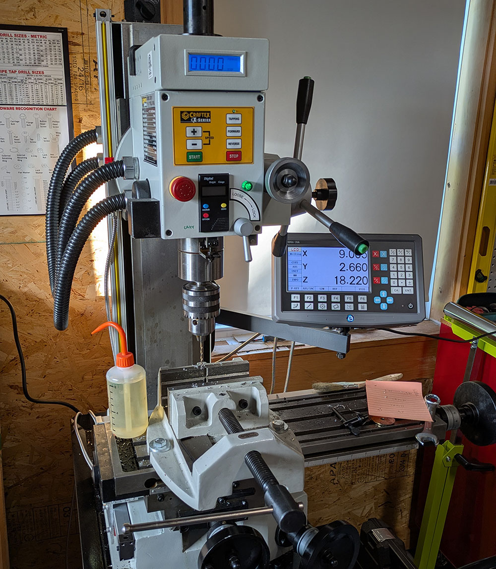
DRO mounted on my Busy Bee CX611 Mill.
DRO Review
I upgraded my mill from a smaller mill to the Busy Bee CX611, which is equivalent to the Sieg SX3. I knew I’d want a DRO, as my previous mill had a simple iGaging DRO which just gave you X/Y/Z readout and a button for inc/abs + setting zero.
I decided to go for one of the larger DRO units for the new mill. My particular one was from “DRO Scale Kit Flagship Store” on AliExpress, and looks something like this on the ordering page (note the display looks different from the one I got):
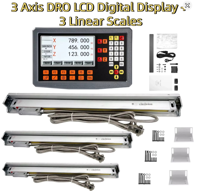
DRO set as it appears on the Aliexpress store.
I’ve been incredibly impressed with this unit. Besides the normal X/Y/Z readout and simple inch/abs offset, it has a lot of features to make life easier. Coming from the very basic “set to zero” only functionality, having a full keypad is a bigger upgrade than I expected. Some features in particular:
- Set axis to an arbitrary point, so you can basically “read off” drawings.
- One-button divide-by-2, which is useful for finding center when you measure from one side to another.
- Calculator that lets you copy numbers from each axis, and write results back to the axis.
- Save a lot (500) presets which are offset from a set base - can program in points to go to. This lets you program locations from a drawing upfront, which is very hand as you can do your setup first, then do the machining without having to stop and reprogram things.
- Circle and array modes.
That isn’t everything, but those are the ones I found most useful. Once you have this it’s hard to imagine going back to a simple DRO (just as it was hard to imagine going back to dials only when I setup my simple DRO!).
If note it also had a ’lathe’ feature which let you add two scales together (so the X can be a combination of the saddle plus compound rest). I went with smaller iGaging scales for my lathe however as they fit better, so can’t comment on that use.
DRO Ordering
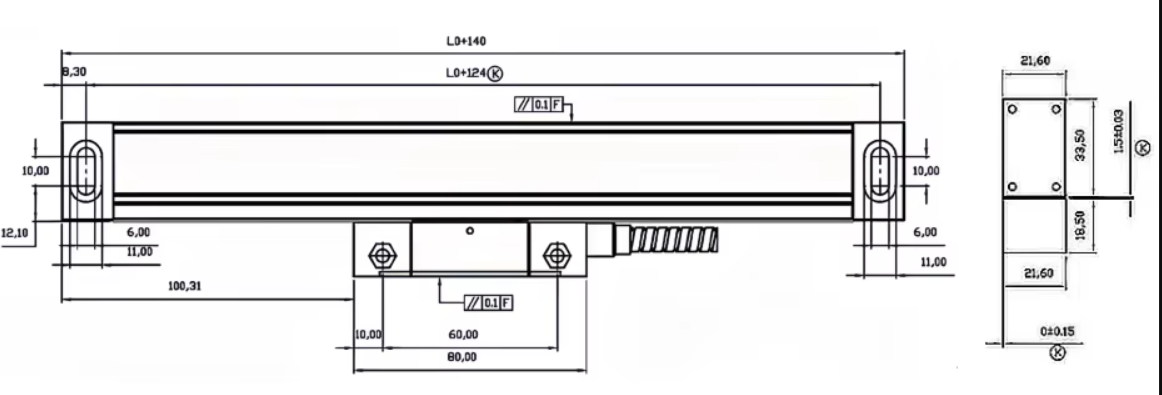
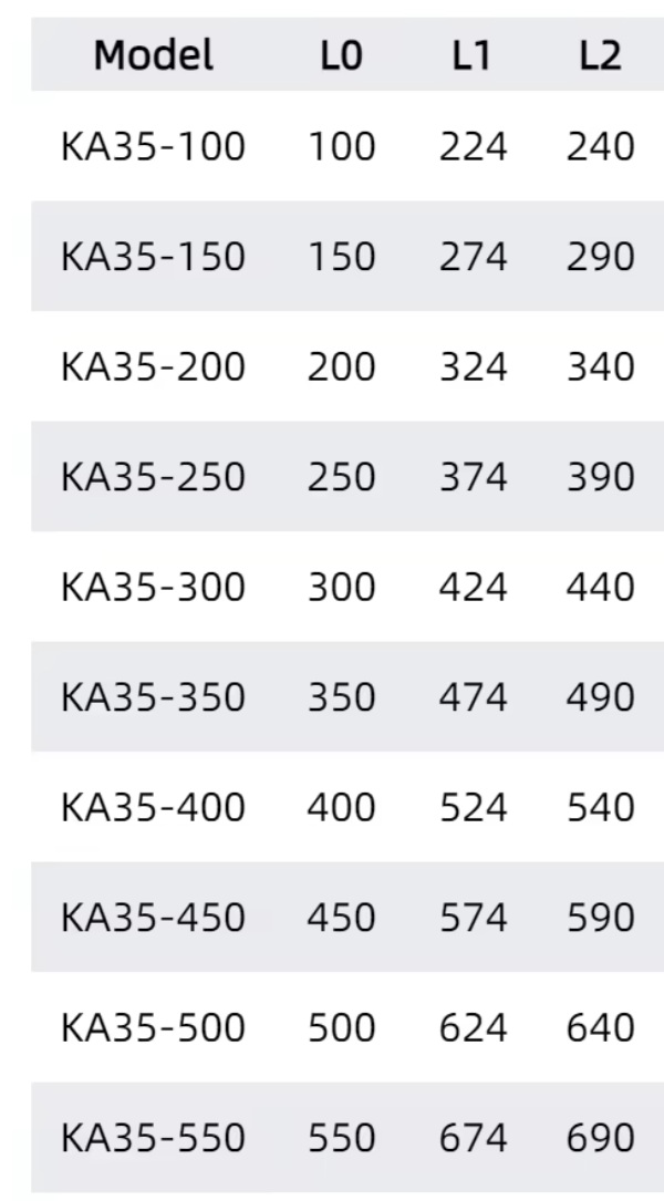
When ordering the DRO, you can specify the length of the scales you need. There isn’t a charge for longer/shorter scales when I bought it. For reference, the following images show the drawing on the aliexpress seller site and their table:
I bought the following sizes:
- KA-150 for Y axis (150mm travel)
- KA-400 for X axis (400mm travel)
- KA-550 for Z axis (550mm travel)
All of those were larger than the total travel length, and appeared like they would fit well on the machine. Installation shows this in detail.
DRO Installation
The install kit came with a variety of hardware. The mounting bolts were M4, I mostly used M4 bolts for mounting. Get a good quality plug tap for doing this, as it makes life much easier. I used a #30 drill.
X Axis
The X axis was the easiest. I mounted the scale to the backside of the table:
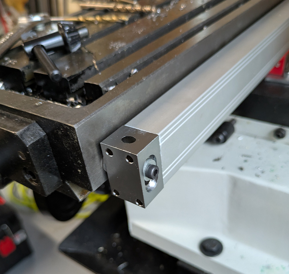
I then used a flat piece of aluminum to mount the sensor to the base.
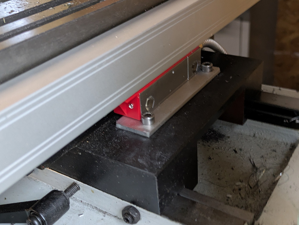
The flat piece of aluminum is secured to the sensor by 2x flat-head M4 screws countersunk into the aluminum. The aluminum plate is then mounted with 2x M4 cap-head screws to the slide.
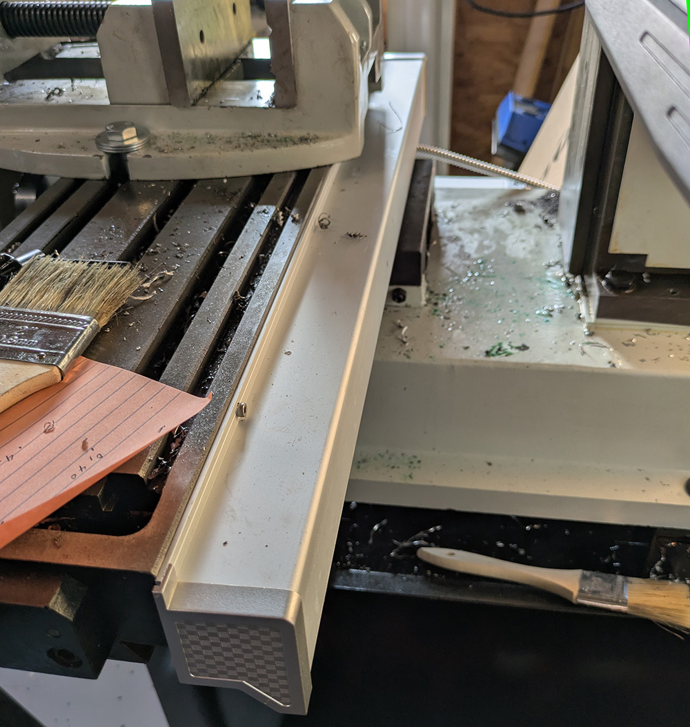
Finally, I was able to put the provided swarf guard over the entire rail. This is the only one that the guard could reasonably fit, and luckily is probably the most exposed:
Y Axis
I mounted the Y axis such that it was pointed downward, as it would be in quite an “exposed” location otherwise to swarf falling into the sensor. I then used some of the provided aluminum pieces to make an adapter to mount to the saddle:
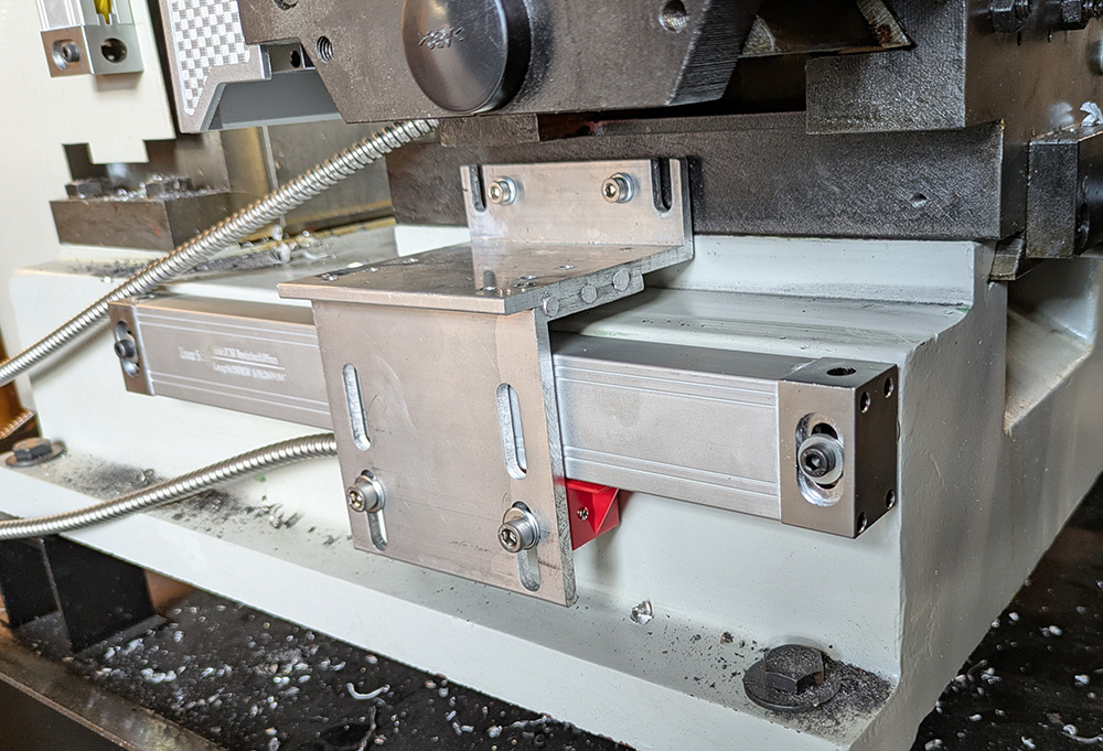
Mounted Y sensor on mill
Z Axis
The Z axis was the first I installed. I mounted it on the left-hand side as that was more out of the way:
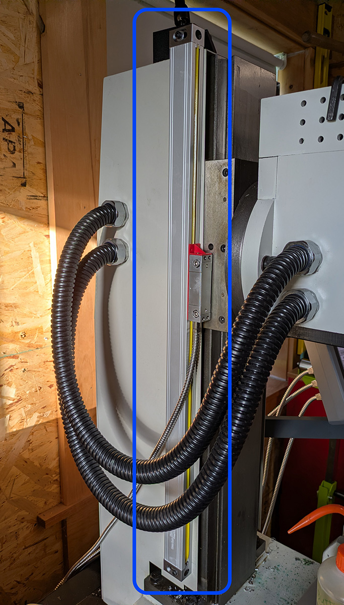
The left side was more out of the way for my normal usage.
I bent a piece of stainless to re-use the existing M4 bolts on the top, which let the slide face outward along the entire side:
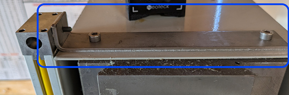
A bent piece of stainless made for a nice mounting bracket.
This was the most “exposed” mounting, swarf could be throw towards the slide. If I have trouble I may eventually flip it around a little more like the Y axis. The bottom hole was just mounted to the sheet metal around the column, which felt rigid enough and avoided needing another bottom bracket.
The sensor was mounted using 2x M4 bolts I drilled/taped into the head. Doing this required drilling out the threaded holes in the sliding sensor to make clearance holes. I drilled them using a 4.0mm metric drill - the bolts themselves are slightly undersized, so this gave a tighter than normal clearance.
They then matched up with the M4 boltholes I tapped into the head, and let me simply bolt the sensor right to the head itself:
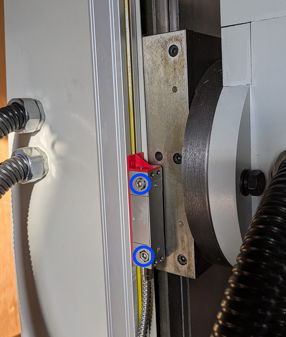
The blue circled holes were threaded, I drilled them out to make clearance holes
This should work even if I used the tilt head feature of this mill.
Display Mounting
I mounted the display to the column itself. The section it was mounted to contains the control electronics. I just removed the rear panel (with it unplugged!), and used M6 cap-head screws to mount the display. This used mostly provided hardware:
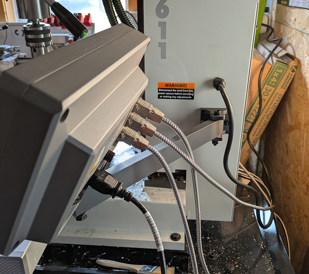
Overall - more straightforward than I expected. A very happy upgrade, you won’t be disapointed.