Adding iGaging EZ-View DROs to a Busy Bee CX706 ( 10 x 18 lathe)
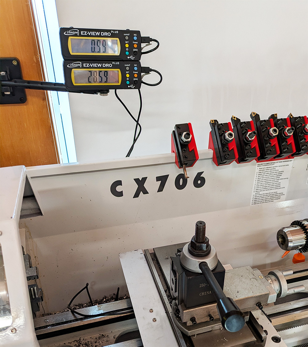
DRO Review
I upgraded my lathe from a smaller lathe to the Busy Bee CX706. At the same time I was adding a DRO to my mill, I also added one to my lathe. The lathe setup was done with a simpler (iGaging) DRO for a few reasons:
- The scales for the larger DRO didn’t seem to fit as well on the lathe.
- The iGaging scales can be cut to size - I wanted to get a more perfect fit so things weren’t sticking out on the cross-slide where they could get in the way.
- Most operations on the lathe feel more suited to a simple DRO - I’m not aligning multiple holes like I am with the mill, so the full-sized DRO felt overkill for me.
- I wasn’t sure if I wanted up to 4 displays in the end (the carriage for sure, but maybe the compound rest as well would get one, + the cross-slide & tail-stock)
The full-sized DRO display is much nicer I admit, a feature I commented on in my mill DRO setup. But some of those reasons (such as hole arrays) isn’t relevant to the lathe, so in the end I was happy with the smaller more “out of the way” scales on my lathe.
DRO Ordering
You will need:
- iGAGING 24"/600mm EZ VIEW DRO PLUS SYSTEM (35-724-P+) x1
- iGAGING 6"/150mm EZ VIEW DRO PLUS SYSTEM (35-706-P+) x2
I ordered from the KBC Tools (Canada), but they are pretty widely available. The “EZ-View” version is well worth it over the older version. The displays are bigger, there are more buttons for switching modes, and there is an additional “data output” you can interface to a better DRO display if you want in the future.
DRO Installation
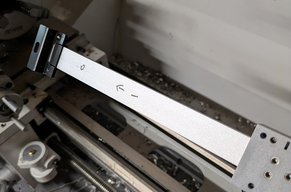
Check which way is “zero” on the scales - unlike the larger DRO you can’t invert this in settings (that I found). Mark this so you end up with the scales as expected:
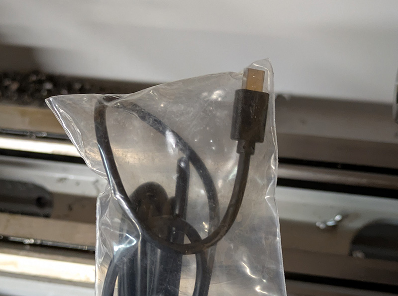
Another trick is that when doing the setup, I stuffed all the cord into a ziplock bag. This meant I wasn’t worried about it falling into a pile of chips or oil as I’m working. You remove the strain relief to unplug the cable.
X Axis (Carriage)
For the X-axis I used the full-sized 24" scale, which fit almost perfectly along the entire backside. I had to “reverse” one mounting bracket to fit:
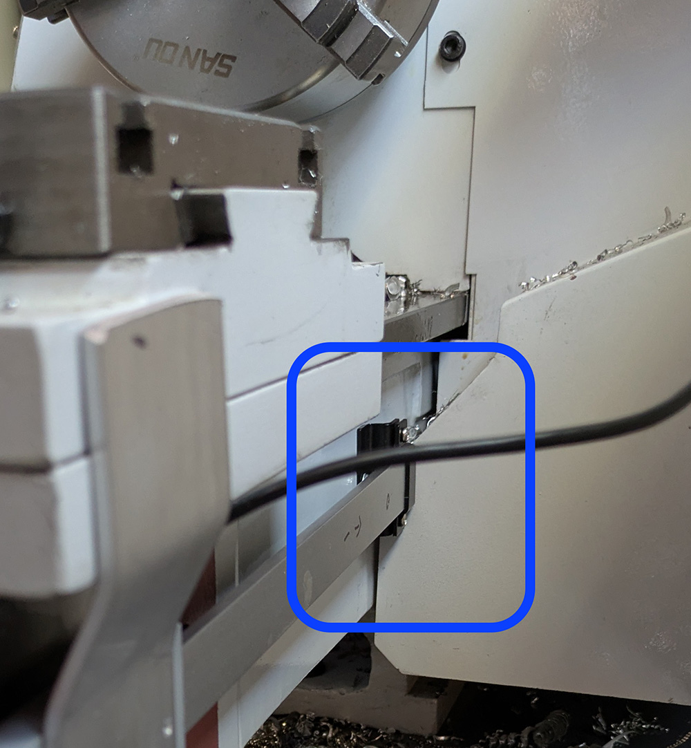
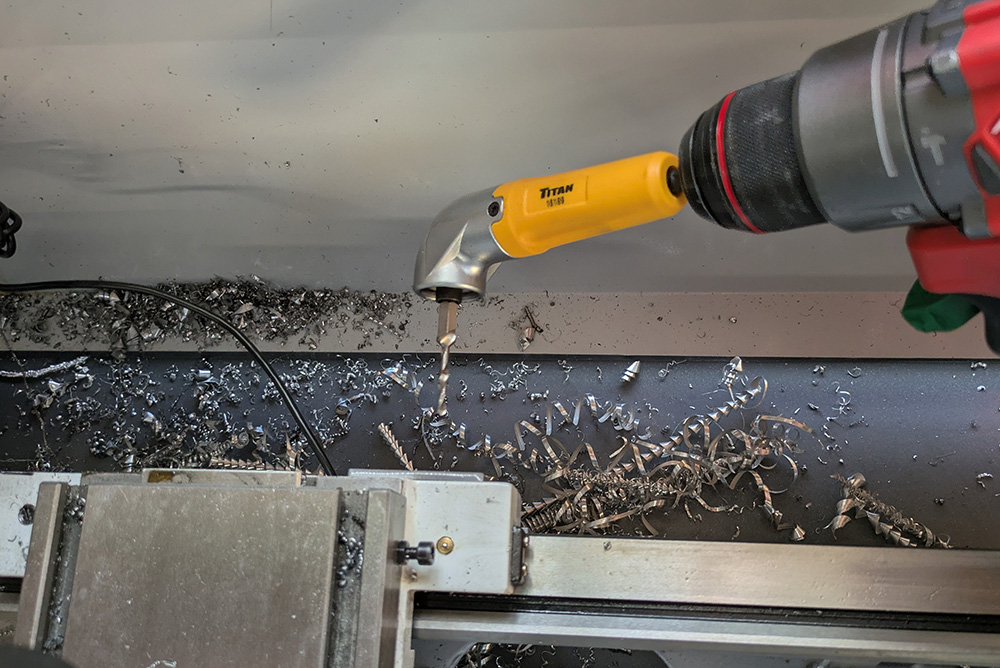
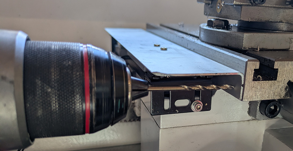
I used a short bit (in this case a drill/tap bit) with a right-angle drill attachment to drill the back without moving the lathe or taking off the back guard. A bit lazy but it worked.
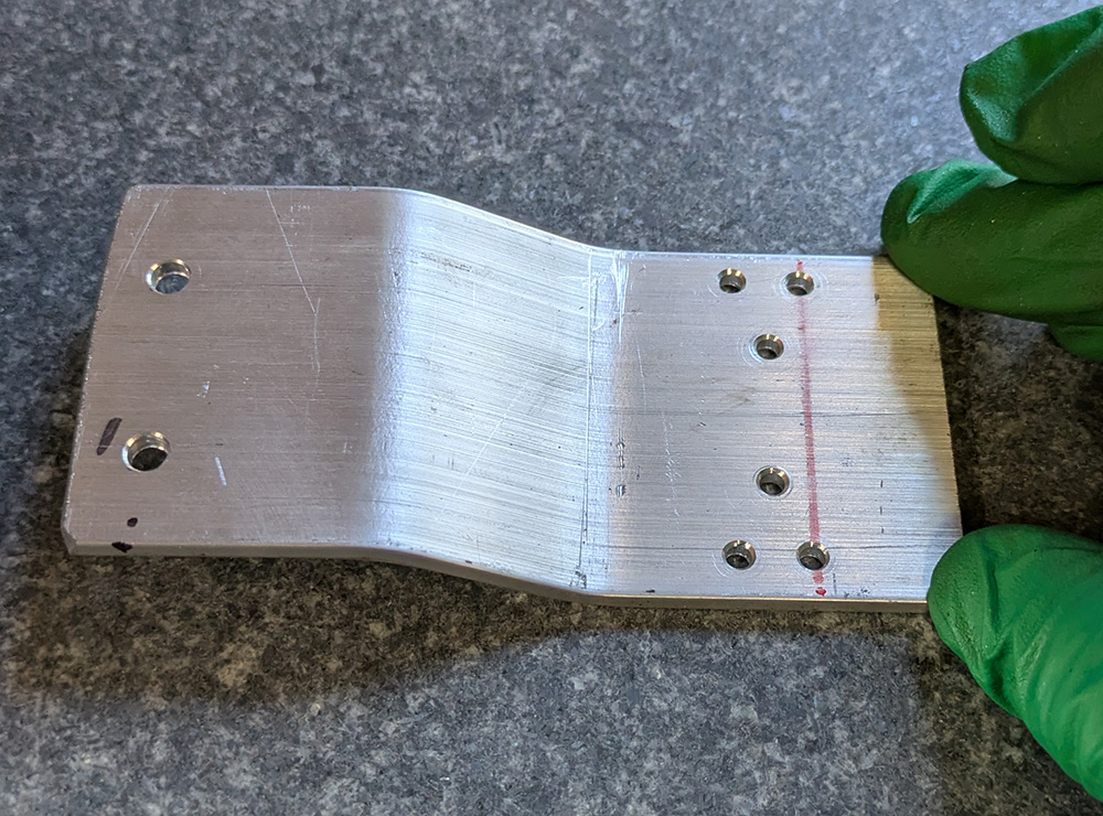
A bent piece of 2" aluminum (1/8" thickness) was my adapter plate - I don’t have dimensions as mostly did it “to fit”:
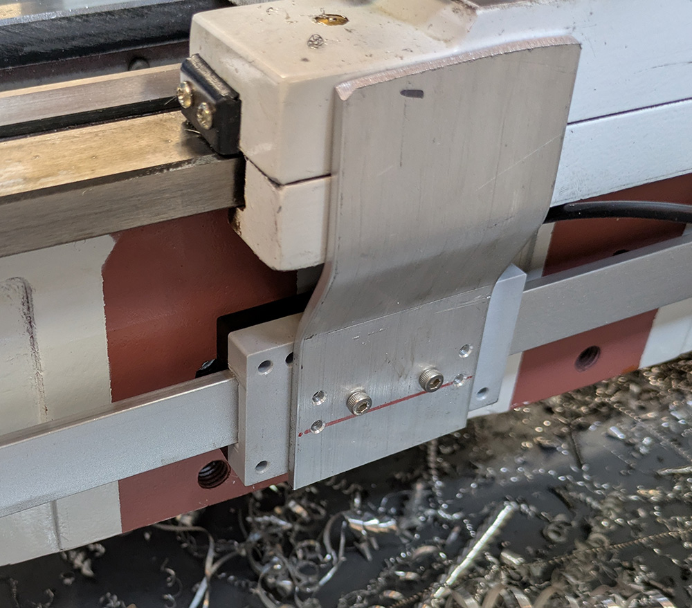
You can see here how it fits - the scale is mounted “backwards” to make it easy to access the mounting bolts.
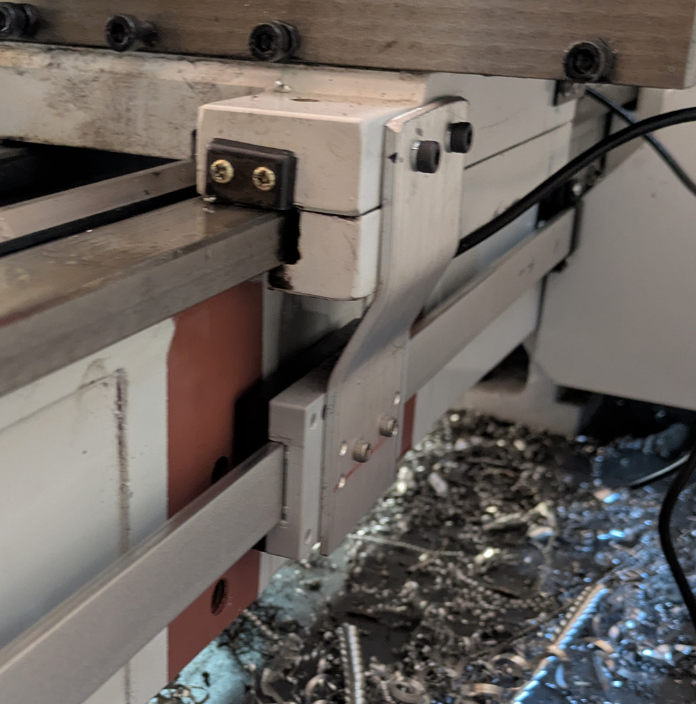
Drill & tap the bolts in the carriage and you’re done:
Y Axis (Cross-Slide)
The cross-slide is the trickier one, as it is more exposed & you don’t want to limit travel. I ended up putting it on the chuck side (keeps some of the adjustment gibs open on the other side). Here was my final mounting solution:
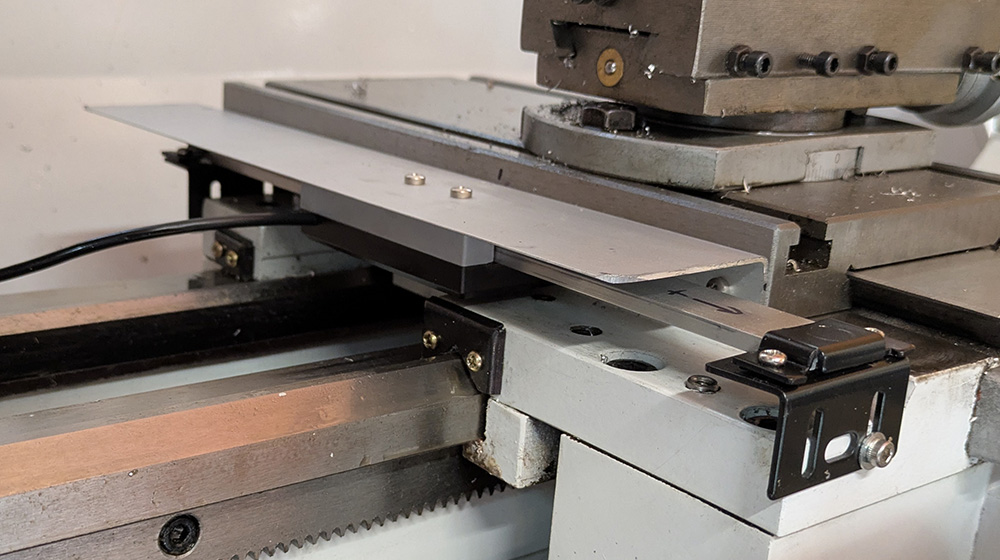
I had to trim this down a little bit to fit. You can cut the iGaging slides - just carefully remove, cut with a hacksaw, deburr, and feed back in. I used the provided mounting brackets still, you’ll see from the photo one is “backwards” to the other.
You can experiment with the travel of the cross-side & how you can keep some of the oiling holes exposed when the slide moves to the far side. Watch where existing oil and other holes go in - it’s a tight fit but you can make it work!
I used some left-over angle/shield piece from the mill DRO install to form the swarf/oil guard. Note this is how the movement actually gets transferred to the slide.
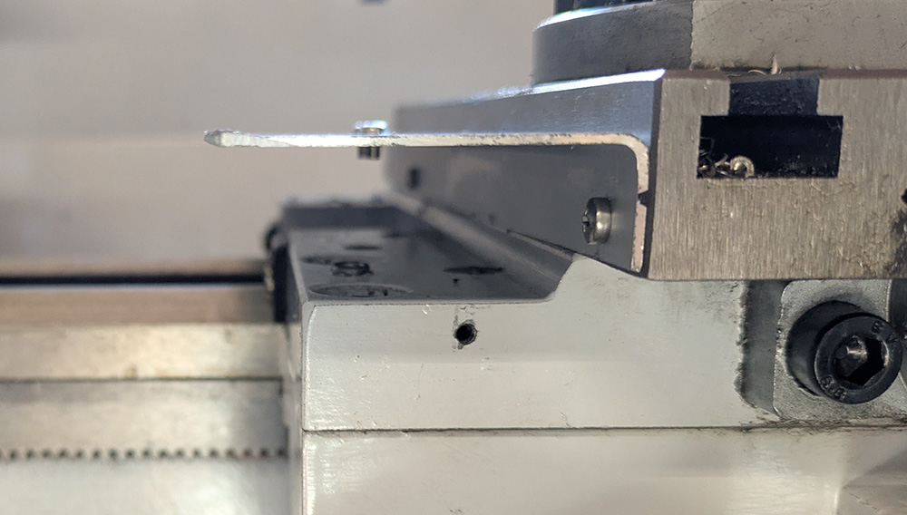
I mounted the bar first, and once that was in it’s easy to figure out the correct alignment and drill holes (being sure to be low enough to miss the slots):
Finally, you can use this as strain relief for the cable:
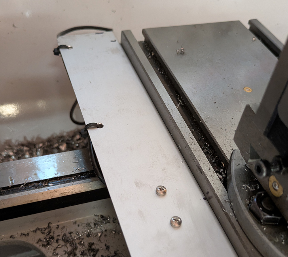
Overall this worked really well. It fits below the chuck (provided jaws don’t extend too much), which isn’t common to get that close but it was something I didn’t want adding a DRO to prevent fully.
Further Work
Once I got both these 2 axis on I could get to work with some projects. So I haven’t finished yet - my next plans are to:
- Mount the tailstock DRO
- Make a better mount for the DRO displays (probably mount them on the back of the lathe instead of the wall)
- Possibly add a compound rest DRO (this is unlikely as it seems like it will get in the way, and I can use the dial when needed)