ESC SV 2015 – USSSSSB: Talking USB From Python

At ESC 2015 SV I gave a talk on using USB From Python, see the talk description here. This blog post is serving as a placeholder to allow me to update links to software used during the live demo.

For SuperCon 2015, there is a Project Page with these details too. You can also ask questions on the project page.

Download Slides

There is two versions of the slides. Use the SuperCon slides, but I left a copy of the ESC ones here in case you wanted the original for some reason.

Download Slides from Hackaday SuperCon 2015 (Newer Version for SAMD21) [PDF, 10MB]

Download Slides from ESC2015 (Older version for SAMD11) [PDF, 10MB]

Tools to Install

  1. Atmel Studio 6.2
  2. WinPython-2.7
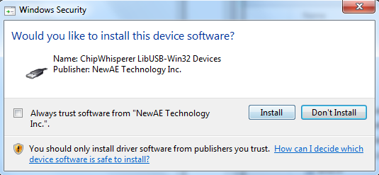
  3. libusb-win32-devel-filter (NB: No need to open the filter install wizard when done)
  4. USBView

SAMD11 Errata

For ESC I used a SAMD11 device, which needs a bit of a hack.

There is a bit of an “oopsie” in the SAMD11 devices. This bug isn’t in the official errata yet, and I’ve been told it’s limited to engineering sample devices (which were used in some of the early dev boards).

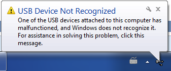
Basically the 48MHz oscillator calibration byte is wrong, and you need to manually tune this. You’ll know this problem exists as the device won’t be detected by Windows:

usbbad

The work-around isn’t super-fun. First, use the programming interface to see the starting value of the DFLL48M_COARSE_CAL fuse:

pllbad

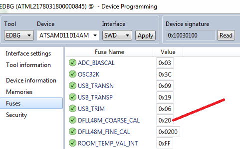
Next, search in the source code for reference to the dfll_conf.coarse_value variable. You will find where it is being setup, and you can override the value. Basically you have to experiment a bit to find a working value:

pllhack

 Reference Code

USB Test – Slide 87

import usb.core
dev = usb.core.find(idVendor=0x03eb, idProduct=0x2402)
print dev

If you get “None”, make sure you installed the “Filter Driver” using the LibUSB tools!

Control Endpoint Read – Slide 94

import usb.core
dev = usb.core.find(idVendor=0x03eb, idProduct=0x2402)
dev.set_configuration()

data = dev.ctrl_transfer(0b10100001, 0x01, 3<<8, 0, 4)

print data

If you get a “device is not functioning” error just skip this one…

Sending Output Report

import usb.core
dev = usb.core.find(idVendor=0x03eb, idProduct=0x2402)
print dev

dev.set_configuration()

data = [ord('1'), ord('1'), 0, 0, 0, 0, 0, 0]
dev.write(0x02, data)

Receiving Input Data (Press button to see change)

import usb.core
dev = usb.core.find(idVendor=0x03eb, idProduct=0x2402)
print dev

dev.set_configuration()

for i in range(0, 10):
    while True:
        try:
            test = dev.read(0x81, 8, timeout=50)
            break
        except usb.core.USBError, e:            
            if str(e).find("timeout") >= 0:
                pass
            else:
                raise IOError("USB Error: %s"%str(e))
     
    print test

 Full GUI Example

#Public domain - simple USB GUI Example by Colin O'Flynn

from PySide.QtCore import *
from PySide.QtGui import *
import usb.core
import sys

class USBForm(QDialog):
    def __init__(self, parent=None):
        super(USBForm, self).__init__(parent)
        self.setWindowTitle("ESC 2015 Demo")

        layout = QVBoxLayout()
        self.setLayout(layout)

        self.pbConnect = QPushButton("Connect")
        self.pbConnect.clicked.connect(self.con)
        self.isConnected = False

        self.pbLED = QPushButton("LED Blinking")
        self.pbLED.setCheckable(True)
        self.pbLED.clicked.connect(self.changeLED)
        self.pbLED.setEnabled(False)

        layout.addWidget(self.pbConnect)
        layout.addWidget(self.pbLED)

        self.swStatus = QLineEdit()
        self.swStatus.setReadOnly(True)
        layout.addWidget(self.swStatus)

        self.butTimer = QTimer(self)
        self.butTimer.timeout.connect(self.pollButton)


    def con(self):
        if self.isConnected == False:
            #Do USB Connect Here
            self.dev = usb.core.find(idVendor=0x03eb, idProduct=0x2402)
            self.dev.set_configuration()

            #Sync changeLED
            self.changeLED()
            
            self.isConnected = True
            self.pbConnect.setText("Disconnect")
            self.pbLED.setEnabled(True)
            self.butTimer.start(100)
        else:
            self.isConnected = False
            self.pbConnect.setText("Connect")
            self.pbLED.setEnabled(False)
            self.butTimer.stop()

    def changeLED(self):
        if self.pbLED.isChecked():
            #Send command to make LED on
            self.dev.write(0x02, [ord('1'), ord('1'), 0, 0, 0, 0, 0, 0])

            self.pbLED.setText("LED On")            
        else:
            #Send command to make LED blink
            self.dev.write(0x02, [ord('0'), ord('1'), 0, 0, 0, 0, 0, 0])
            self.pbLED.setText("LED Blinking")

    def pollButton(self):
        try:
            data = self.dev.read(0x81, 8, timeout=50)
            if data[0]:
                self.swStatus.setText("Button Pressed")
            else:
                self.swStatus.setText("Button Released")
                
        except usb.core.USBError, e:
            if str(e).find("timeout") >= 0:
                pass
            else:
                raise IOError("USB Error: %s"%str(e))


if __name__ == "__main__":
    app = QApplication(sys.argv)
    form = USBForm()
    form.show()
    sys.exit(app.exec_())

Side-Channel Power Analysis of AES Core in Project Vault

What is Project Vault

You can read a quick overview on various news sites, but basically project vault gives you a cryptographic module that you have complete control over. This means *you* decide to trust the module – even to the point of being able to access to implementation details of the crypto cores.

Basically Project Vault is a solution to how you can avoid having unknown backdoors in your hardware. Rather than having to trust some vendor of security modules, you can make sure things are done correctly.

About the AES Core

The crypto modules have a nice description, which you can read here. Of interest to us is this statement:

The AES core can encrypt and decrypt blocks of data in three modes of operation: AES-128, AES-192, and AES-256.  The design is based upon a purely gate logic implementation of the forward and reverse sboxes due to the work of Boyar and Peralta.  This avoids differential power attacks present in purely lookup table or SRAM based sbox implementation.

The paper in question isn’t written by Andy Samberg’s character on Brooklyn Nine-Nine, but instead is referencing A small depth-16 circuit for the AES S-Box (that link is the unpaywalled version, the paper was published in the SEC 2012 proceedings).

This is a problematic statement, as side-channel power leakage isn’t just one simple fix. In this case there is effectively no difference from an unprotected implementation for side-channel power analysis. More on that in a moment.

Side-Channel Power Analysis

It’s worth pointing out I’m looking at a single small part of the entire device. There may be additional protocol-layer protection that would significantly complicated the analysis I perform, I just have no idea as haven’t looked into that.

Realistically, side-channel power analysis might be a threat. Having a leaking core on it’s own might be impossible/very difficult to exploit due to use-cases. But it might form part of a larger attack (i.e. someone is able to take control of the core using a different attack method).

Side-channel power analysis (or Differential Power Analysis, called DPA) also requires the device is operating with the key we are using. You cannot use DPA on an encrypted hard drive sitting on the table for example – you could only use it to recover the encryption key as the drive is decrypting/encrypting something. If the encryption key comes from the user, this means DPA is useless against an encrypted drive you recovered from someone.

Because of these caveats I like to stress this isn’t some master attack. In fact the only thing that makes it noteworthy is the documentation claimed some level of DPA resistance. Anyway on with the attack…

Attack Theory

DPA attacks are based on small power measurements being correlated with either data values or changes in data. In the referenced paper from earlier, the DPA attack being prevented is that the input and output of the S-Box are never put onto the same register.

This means we could never see the difference in number of bits flipped from input to output of the S-Box. Thus the power analysis attack on the S-Box itself would fail, which is normally where an easy leak to stop is. But it’s not the only way.

Looking at the source code, we see the following Verilog lines during the encryption (similar lines for decryption):

            begin
                state <= state_new;
                if(round == round_max)
                beginS
                    data_o <= state_new;
                    busy_o <= 0;
                end
            end

This is problematic, as the 128-bit AES state is held in a register. That register is overwritten on each round. In particular, looking at the last round (this figure based on one shamelessly stolen from Frank Gürkaynak’s Thesis), note the “old value” to “new value”:

aes_state_desc

The ShiftRows is easily reversed (it’s just swapping around the location of bytes). This in fact means the input and output of the S-Box is effectively written into the same register, giving as an easy way to count bit flips (Hamming Distance). We can correlate expected number of bit transitions with measured power as in a standard DPA attack.

Attack Test

While it’s not really needed to test this in theory, nobody believes hand-waving. So I used a SAKURA-G FPGA board (Spartan 6 LX75) with my OpenADC and ChipWhisperer software, as I happen to have it around:

You could easily use my ChipWhisperer-Lite with any other FPGA board instead of the SAKURA-G. The SAKURA-G makes power measurement easier, otherwise you can use some H-Field probes etc.

There’s not a lot to this – I ripped out just the AES core (i.e. everything in this directory in the GIT). It’s easy to interface to the existing FPGA code given with the SAKURA-G, as the interface is almost exactly the same (key in, block in, block out, clk, go command).

There was a few cycles of synchronization error for some reason, but I used a “resync by sum of absolute difference” in my ChipWhisperer software. Here is what the raw power traces look like after resync:

aes-power

Running an attack targeting the last round-state difference of AES gives us a nice figure where the known encryption key bytes (in red) are filtering to the top of the “most likely encryption keys”, here with 2000 traces:

aes-pge

You can check where the leakage is occurring too. In the following figure the “correct” byte value is highlighted in red. You can see around sample ~342 there is the largest absolute peak of that correlation value, and it rises about all the wrong guesses. This corresponds to around the last round (based on power dips in earlier waveform):

aes-locationThat’s it! It’s really a standard Hamming-Distance attack against AES. The special S-Box design didn’t make our life any harder for my attack. Again this was done in a controlled environment, so it’s quite possible there are higher-level protections that make this attack much much harder.

Considering the device will (presumably) only have the encryption keys loaded when the user is doing stuff, it’s a pretty small risk. An attacker would have to monitor the power while you are using the device to deduce your keys… and if they are that close, they might just try seducing you instead.


Experiments with Seek Thermal Camera

A while back I got a Seek thermal camera, as I wanted to use it for measuring electronics component temperatures. As part of a course I’m teaching at Dal, I did a few experiments I wanted to post here. These photos were taken with a macro lense, shown here:

seeker

To get that lens, I purchased a 20mm diameter ZnSe Lens with 50.8mm/2″ focus off E-Bay for about $20. I ended up getting both a 100mm and 50mm focal length to try both. Then you need a holder, which I used one I found on Thingiverse. If printing again I’d try to enlarge the size of the space for the lens – I had to use a knife and considerably carve the inside step down. In fact I’d remove the middle ‘ridge’ which holds the lens in, and instead epoxy it.

The Tests

I’m using a TO-220 5 ohm resistor, which lets me reliably control the power being dissipated by the device. The part number is PF2205-5R which you can get at Digikey.

The first test compares mounting the resistor horizontally and vertically. To do this I’ve put two into a breadboard:

restest_overview

Which we power with constant power using my supply:

restest_powerinAnd can see the difference in temperature between the two:

restest_results

So what gives? There is (expected) to be two reasons for the temperature difference:

  1.  The vertical mount naturally causes airflow over the large back tab – heat will rise, and as heat comes off the tab, it cause a small amount of natural airflow.
  2. The horizontal mounted package is closed to the table surface which will further restrict airflow.

The majority of this comes from #1, but people will complain if I don’t mentioned #2. If your heatsinks has lots of fins, it’s worthwhile to ensure the natural airflow due to heat easily flows up the heatsink.

Also note the temperature rise is about what is expected of a TO220 package, which typically has about a 62ºC/W Junction to Case thermal resistance. Ambient is around 20C, so with 1W of power in we expect 20ºC + 62ºC = 82ºC case temperature. Cool!

The second test tries several mounting of TO220 packages on a PCB. The PCB setup is shown here:

restest_more

First, let’s look at the vertically mounted device. Here is the thermal image once it reaches steady-state:

restest_vert

What the hell happened? We still had 1W of input per transistor, but it’s 14C cooler than the other test!

In this case the PCB is dissipating some of the heat – the entire top and bottom are solid copper pours, each side connected to one of the pins. This is almost idea for heat transfer.

Next, let’s look at the other two resistors. The following shows both details of the mounting and the steady-state temperatures:

restest_doubleI should mention the reflection areas have low thermal emissivity, and the Seek camera doesn’t pick them up correctly. Thus the tab & PCB area without solder-mask aren’t actually cooler.

Anyway you can see that mounting the package *close* to a good heatsink but without actually touching it is worse than free-space mounting. Having a good connection (in this case soldering) as expected further reduces the case temperature by allowing the PCB to dissipate more of the heat.

The “close but not touching” comes up a lot – for example if you make a simple metal shield for your device, you might think it a good idea to have the shield come close to heat-producing devices. But unless it actually makes good contact, you are probably hampering the natural convection air currents!

When I get some more time I plan on buying a few different heatsinks from Digikey and compare my measured temperature rise with the theoretical temperature rise.

USB Inrush Testing

The USB spec has limits on the ‘inrush current’, which is designed to prevent you from having 2000uF of capacitance that must be suddenly charged when your board is plugged into the USB port.

The limit works out to around 10uF of capacitance . Your board might have much much more – so you’ll have to switch portions of your board on later with FETs as a soft-start.

For the ChipWhisperer-Lite, I naturally switch the FPGA + analog circuitry as to meet the 2.5 mA suspend current. Thus I only have to ensure the 3.3V supply for the SAM3U2C meets the inrush limits, which is a fairly easy task. This blog post describes how I did this testing.

The official USB Test Specs for inrush current testing describe the use of the Tektronix TCP202 which is $2000, and I don’t think I’d use again a lot. Thus I’m describing my cheaper/easier method.

First, I used a differential probe (part of the ChipWhisperer project, so you can see schematics) to measure the current across a 0.22 ohm shunt resistor. The value was selected as I happened to have one around… you might want a smaller value (0.1 ohm say) even, as the voltage drop across this will reduce the voltage to your device. The differential probe has enough gain to give your scope a fairly clean signal. This shows my test board, where the differential probe is plugged into a simple 2-pin header:

P1080537

From the bottom, you can see where I cut the USB shield to bring the +5V line through the shunt:

P1080538

To calibrate the shunt + gain from the diff-probe, I just used some test loads, where I measure the current flowing through them with a DMM. You can then figure out the equation for converting the scope measurement to a current in amps.

P1080539

Finally, we plug in our actual board. Here I’ve plugged in the ChipWhisperer-Lite prototype. The following figure shows the measurement after I’ve used a math channel in PicoScope to convert the voltage to a current measurement, and I’ve annotated where some of these spikes come from:usb_power

Saving the data, we can run through the USB Electrical Analysis Tool 2.0 to get a test result. The USB-IF tool assumes your scope saves the files with time in seconds and current in amps. The PicoScope .csv files have time in miliseconds, so you need to import the file into Excel, divide the column by 1000, and save the file again. Finally you should get something like this:

compliance_results

Note the inrush charge is > 50mC, but there is an automatic waiver for anything < 150 mC. While the system would be OK due to the waiver, I would prefer to avoid exceeding the 50 mC limit. In this case there’s an easy solution – I can delay the USB enumeration slightly from processor power-on, which limits the inrush to only the charging of the capacitors (which is done by ~15mS). This results in about 47 mC. This means I’ve got about 100 mC of headroom before I exceed the official limits!

This extra headroom is needed in case of differences due to my use of the shunt for example.

In addition, I should be adjusting the soft-start FET gate resistor to reduce the size of that huge soft-start spike. Ideally the capacitor charging shouldn’t draw more than the 500mA I claim when I enumerate, so that’s a little out of spec as-is! If I don’t want to change hardware I could consider using PWM on the FET gate even…

Driver Signing Notes

I recently wanted to sign some drivers to avoid requiring users of my ChipWhisperer device to do the usual bypass-signature deal. The end result is a sweet sweet screen like this when install the drivers:

usbsig

If you are in this situation, I wanted to add some of my own notes into the mix.

David Grayson has an awesome guide which I mostly followed, available at http://www.davidegrayson.com/signing.

The steps I followed (again from his guide basically) are:

  1. Buy a Code Signing Certificate, I selected one from GlobalSign. They will verify your company information as part of this (or name if person) which basically involves calling you.
  2. Download the certificate. You can then double-click on it to install it into your system (hint: you may want to dedicate a VM or machine to this to keep your certificate off your laptop you travel with for example).
  3. You need the ‘signtool’ and ‘inf2cat’ programs. This requires install Windows SDK + Windows WDK (which itself depends on Visual Studio 2013). There’s like 10GB of other crap you install in order to get these files. Anyway install them…
  4. Write the following in a batch file:
    "C:\Program Files (x86)\Windows Kits\8.1\bin\x86\inf2cat" /v /driver:%~dp0 /os:XP_X86,Vista_X86,Vista_X64,7_X86,7_X64,8_X86,8_X64,6_3_X86,6_3_X64
    "C:\Program Files (x86)\Windows Kits\8.1\bin\x86\signtool" sign /v /n "Your Company Name Inc." /tr http://timestamp.globalsign.com/scripts/timestamp.dll *.cat
    "C:\Program Files (x86)\Windows Kits\8.1\bin\x86\signtool" sign /v /n "Your Company Name Inc." /tr http://timestamp.globalsign.com/scripts/timestamp.dll /fd SHA256 /as *.cat
    pause
    
  5. Copy the batch file to the directory with the .inf file, and double-click it.
  6. You might need to modify your .INF file, check the output for errors – I had to update the date to be past 2013 for example. The above will work if you’ve installed the certificate on your system, as it will search for a certificate with “Your Company Name Inc.”, so you need to match that exactly.
  7. Party – you should now have a signed .cat file! Distribute the whole batch (be sure to remove the .bat file) to your customers/users.

The batch file I use above signs both a SHA1 and SHA256 signature. SHA1 is being deprecated due to collision attacks (interesting sidenote: these were used as part of the attack on Iranian centrifuges by creating digitally signed drivers).

Unfortunately SHA256 isn’t fully supported across all platforms you might need to support (see https://support.globalsign.com/customer/portal/articles/1499561-sha-256-compatibility), so for now I’m using both, which I think works?

New Site Layout Live

For some time I’ve been planning on updating my website design. Ultimately I want to move towards more blog posts and less static pages, this is the result. This should help showing some of my projects and videos off a little easier. The old site will remain accessible at http://www.colinoflynn.com/oldsite as I haven’t migrated everything.

In addition this means old links can easily be fixed by inserting ‘oldsite’ into them! I.e. if you have a link to http://colinoflynn.com/tiki-index.php?page=15dot4tools, just change it to http://colinoflynn.com/oldsite/tiki-index.php?page=15dot4tools and everything works!

Let me know if anything breaks though, but in the mean-time I’ll be slowly trying to migrate additional content.

SMD Solder Paste Stencil Creation with Silhouette Cameo

I made some additional details in a long YouTube movie:

This is far from the first blog post on this, but I wanted to write down exactly what I did to get this working on Windows 7, 64-bit with as little fussing as possible.

1. Buy Silhouette Cameo [NOTE: The v1 I used is no longer available. I’ve heard the V2 with latest firmware does work OK]

2. Decide on material. I originally used the Transparency Film but it’s a little thick, so instead ended up finding that you can buy 3 Mil drafting file individually from art stores.

3. Install USB drivers from CD that came with system – this seems to be required, as installing the software from the website alone wasn’t enough. If you need them I’ve mirrored a copy here.

4. Plug in Cameo device. Check if it appears as a printer:

Image
If it DOES NOT, screw around with drivers. For me it appeared as “USB Printer Support” for a while, you’ve got to try updating the drivers and forcing it to use the ones from the CD it seems. Eventually you should have success.

5. Share the Cameo device under “Printer Properties”:

Image

6. Install gerbv

7. Install pstoedit 64-bit or pstoedit 32-bit as appropriate

8. Install Ghostscript 64-bit or Ghostscript 32-bit as appropriate

9. Download copy of gerber2graphtec repo, unzip it somewhere. I’ve linked to my fork of the repo which contains some extra stuff, so if you want the original check the gerber2graphtec pmonta repo

10. Run the GUI. You’ll need to modify paths probably, or at least version numbers. Set the folder share option to match your computer name / printer share:

Image

11. If you haven’t loaded the Cameo before, basically check out the booklet that came with it. Set the cutting depth to ‘1’ on the blade and shove it into the machine. Peel back the blue sheet off the ‘cutting mat’, and stick the transparency to the mat.

12. Load a test gerber, convert it (check the output of the command line doesn’t have errors), and send onward! For me things ‘just worked’.

13. You can use the generate test square feature I added to generated the test pattern. Forces increase from 1 to 30 as it draws the squares.

Rigol DP832 Review

The majority of the review is available in movie format:

I purchased a Rigol DP832 power supply from RAE Electronics (local supplier). I had a chance to play around with it and wanted to leave a bit of a review.

To begin, I also bought some useful accessories. I got them from Digikey, and here are the part numbers:

  • Test Leads: Ponoma B-24-x, where x changes for color
  • Aligator Clips: Digikey 461-1208-ND
  • Minigrabbers: Ponoma 4723-0 / 4723-2

I think those are the most useful accessories to get. Buy at least 4 supply cables, maybe more as if you want to have +/- supplies it’s nice to have a colour for ‘0v’.

I ended up making a GUI, which is available at: https://github.com/colinoflynn/dp832-gui :
Image


Hackaday Project and Latest Circuit Cellar Columns

I had entered my side channel analysis project called ChipWhisperer into the Hackaday Prize. I’m honoured to have been selected as one of five finalists! This means lots more work getting everything ready, but should be exciting.

Since my last post, I’ve also published a few more columns in Circuit Cellar. If you aren’t familiar with my Programmable Logic in Practice column, I post some details of it on my dedicated website. I just posted a video for the Dec 2014 column which includes some experiments with metastability on the Xilinx FPGA. Fun times!

PicoScope 2204A Review

Image

I’ve been spending some time with a low-cost PicoScope device, and wanted to give a review in case you’re looking at one. To begin with, you can check out my Circuit Cellar Articles about selecting a scope.

There’s also a video version of this:

Introducing the 2200 Range

PicoTech’s 2200 range is a compact oscilloscope, if you want all the details check out The PicoTech Website. Presumably you’re interested in my hands-on experience instead though, so I won’t duplicate everything there.

Continue reading PicoScope 2204A Review