A while back I got a Seek thermal camera, as I wanted to use it for measuring electronics component temperatures. As part of a course I’m teaching at Dal, I did a few experiments I wanted to post here. These photos were taken with a macro lense, shown here:
To get that lens, I purchased a 20mm diameter ZnSe Lens with 50.8mm/2″ focus off E-Bay for about $20. I ended up getting both a 100mm and 50mm focal length to try both. Then you need a holder, which I used one I found on Thingiverse. If printing again I’d try to enlarge the size of the space for the lens – I had to use a knife and considerably carve the inside step down. In fact I’d remove the middle ‘ridge’ which holds the lens in, and instead epoxy it.
The Tests
I’m using a TO-220 5 ohm resistor, which lets me reliably control the power being dissipated by the device. The part number is PF2205-5R which you can get at Digikey.
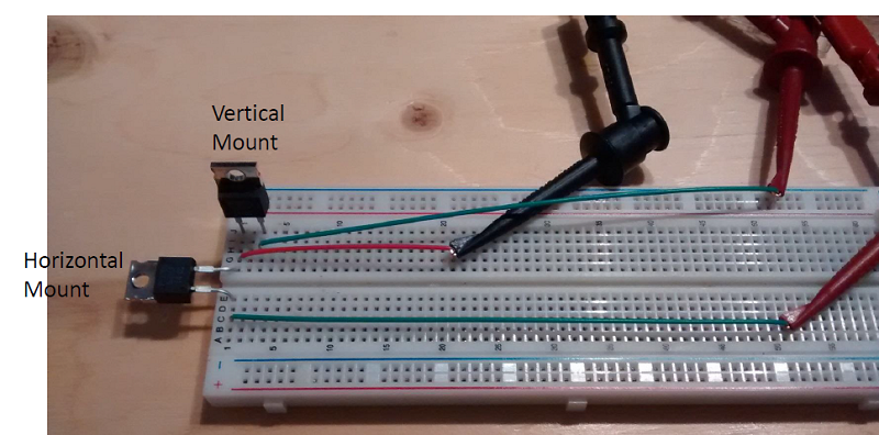
The first test compares mounting the resistor horizontally and vertically. To do this I’ve put two into a breadboard:
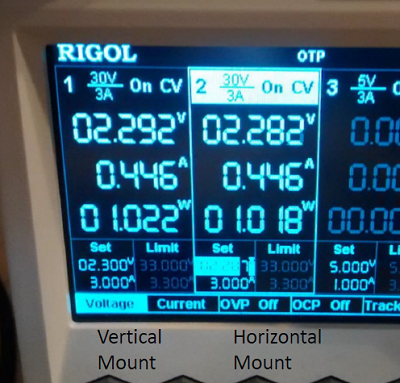
Which we power with constant power using my supply:
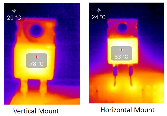
 And can see the difference in temperature between the two:
So what gives? There is (expected) to be two reasons for the temperature difference:
- The vertical mount naturally causes airflow over the large back tab – heat will rise, and as heat comes off the tab, it cause a small amount of natural airflow.
- The horizontal mounted package is closed to the table surface which will further restrict airflow.
The majority of this comes from #1, but people will complain if I don’t mentioned #2. If your heatsinks has lots of fins, it’s worthwhile to ensure the natural airflow due to heat easily flows up the heatsink.
Also note the temperature rise is about what is expected of a TO220 package, which typically has about a 62ºC/W Junction to Case thermal resistance. Ambient is around 20C, so with 1W of power in we expect 20ºC + 62ºC = 82ºC case temperature. Cool!
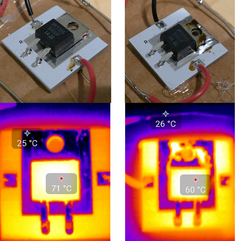
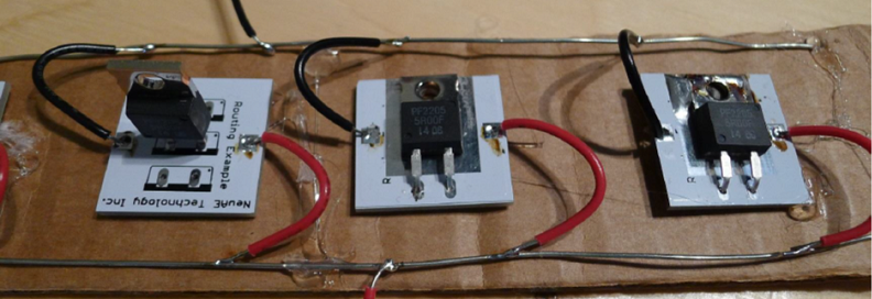
The second test tries several mounting of TO220 packages on a PCB. The PCB setup is shown here:
First, let’s look at the vertically mounted device. Here is the thermal image once it reaches steady-state:
What the hell happened? We still had 1W of input per transistor, but it’s 14C cooler than the other test!
In this case the PCB is dissipating some of the heat – the entire top and bottom are solid copper pours, each side connected to one of the pins. This is almost idea for heat transfer.
Next, let’s look at the other two resistors. The following shows both details of the mounting and the steady-state temperatures:
 I should mention the reflection areas have low thermal emissivity, and the Seek camera doesn’t pick them up correctly. Thus the tab & PCB area without solder-mask aren’t actually cooler.
Anyway you can see that mounting the package *close* to a good heatsink but without actually touching it is worse than free-space mounting. Having a good connection (in this case soldering) as expected further reduces the case temperature by allowing the PCB to dissipate more of the heat.
The “close but not touching” comes up a lot – for example if you make a simple metal shield for your device, you might think it a good idea to have the shield come close to heat-producing devices. But unless it actually makes good contact, you are probably hampering the natural convection air currents!
When I get some more time I plan on buying a few different heatsinks from Digikey and compare my measured temperature rise with the theoretical temperature rise.


Can You share your code with me?
I have got seek thermal starter kit baseboard
I cannot take images from seek camera
please help me
I didn’t use the baseboard – I only used the camera app.
I’m using raspberry pi with python code
Thanks for your nice sharing.
I wonder which focal length to choose, between 50mm or 100mm ?
Thanks for your nice sharing.
I wonder which focal length to choose, between 50mm or 100mm ?