The USB spec has limits on the ‘inrush current’, which is designed to prevent you from having 2000uF of capacitance that must be suddenly charged when your board is plugged into the USB port.
The limit works out to around 10uF of capacitance . Your board might have much much more – so you’ll have to switch portions of your board on later with FETs as a soft-start.
For the ChipWhisperer-Lite, I naturally switch the FPGA + analog circuitry as to meet the 2.5 mA suspend current. Thus I only have to ensure the 3.3V supply for the SAM3U2C meets the inrush limits, which is a fairly easy task. This blog post describes how I did this testing.
The official USB Test Specs for inrush current testing describe the use of the Tektronix TCP202 which is $2000, and I don’t think I’d use again a lot. Thus I’m describing my cheaper/easier method.
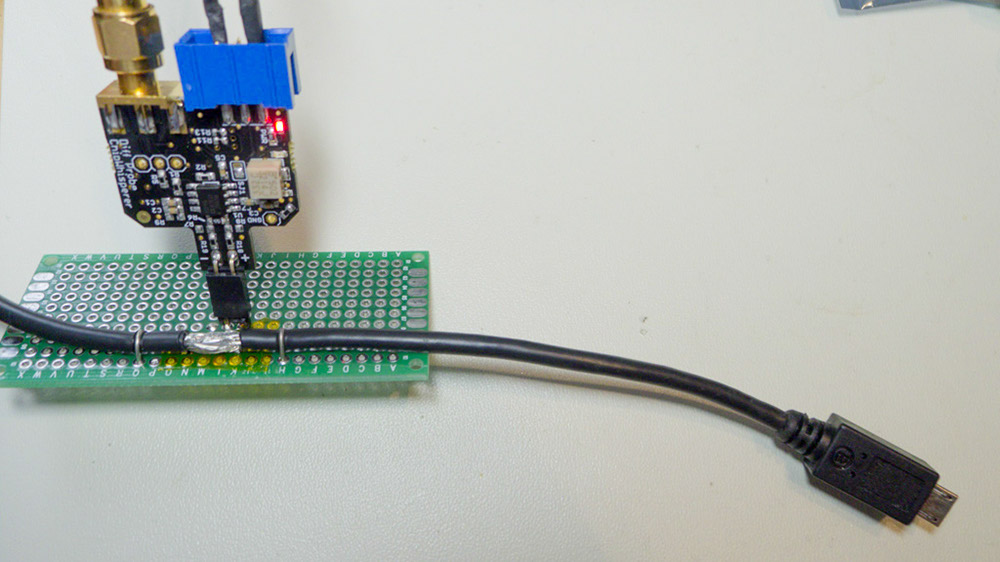
First, I used a differential probe (part of the ChipWhisperer project, so you can see schematics) to measure the current across a 0.22 ohm shunt resistor. The value was selected as I happened to have one around… you might want a smaller value (0.1 ohm say) even, as the voltage drop across this will reduce the voltage to your device. The differential probe has enough gain to give your scope a fairly clean signal. This shows my test board, where the differential probe is plugged into a simple 2-pin header:
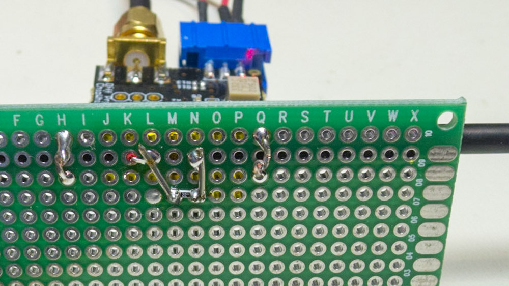
From the bottom, you can see where I cut the USB shield to bring the +5V line through the shunt:
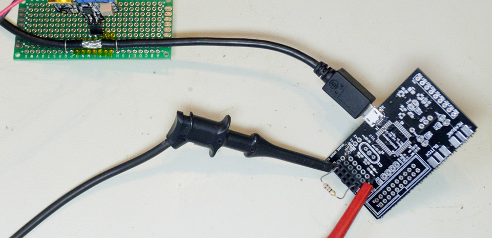
To calibrate the shunt + gain from the diff-probe, I just used some test loads, where I measure the current flowing through them with a DMM. You can then figure out the equation for converting the scope measurement to a current in amps.
Finally, we plug in our actual board. Here I’ve plugged in the ChipWhisperer-Lite prototype. The following figure shows the measurement after I’ve used a math channel in PicoScope to convert the voltage to a current measurement, and I’ve annotated where some of these spikes come from: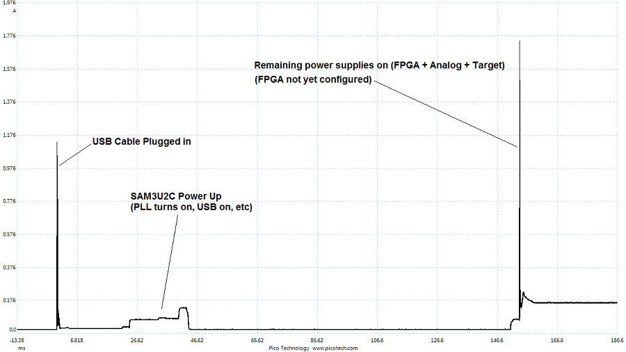
Saving the data, we can run through the USB Electrical Analysis Tool 2.0 to get a test result. The USB-IF tool assumes your scope saves the files with time in seconds and current in amps. The PicoScope .csv files have time in miliseconds, so you need to import the file into Excel, divide the column by 1000, and save the file again. Finally you should get something like this:

Note the inrush charge is > 50mC, but there is an automatic waiver for anything < 150 mC. While the system would be OK due to the waiver, I would prefer to avoid exceeding the 50 mC limit. In this case there’s an easy solution – I can delay the USB enumeration slightly from processor power-on, which limits the inrush to only the charging of the capacitors (which is done by ~15mS). This results in about 47 mC. This means I’ve got about 100 mC of headroom before I exceed the official limits!
This extra headroom is needed in case of differences due to my use of the shunt for example.
In addition, I should be adjusting the soft-start FET gate resistor to reduce the size of that huge soft-start spike. Ideally the capacitor charging shouldn’t draw more than the 500mA I claim when I enumerate, so that’s a little out of spec as-is! If I don’t want to change hardware I could consider using PWM on the FET gate even…