If you’re a bit careless with your CPU (especially if e.g., delidding it) you can knock these resistors off the topside. From measuring a known-good device (but without removing them) I measured the following values as a reference:
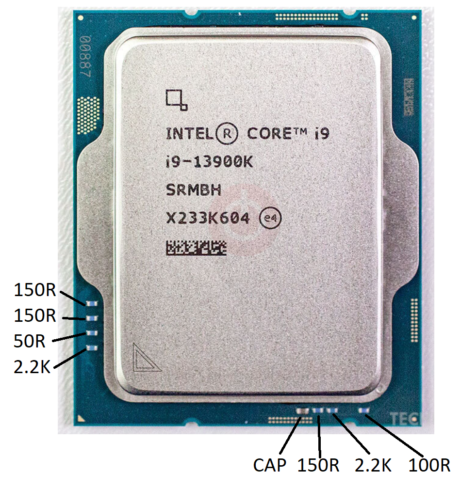
If you’re a bit careless with your CPU (especially if e.g., delidding it) you can knock these resistors off the topside. From measuring a known-good device (but without removing them) I measured the following values as a reference:
NOTE: This was going to be a twitter thread but twitter was down? So this is a lazy blog post…

Anyone used to Digilent would expect this to be based on Zynq or similar – the fact the device has USB + ethernet ports makes it a pretty much sure thing! Taking the screws off the bottom gives us this view:
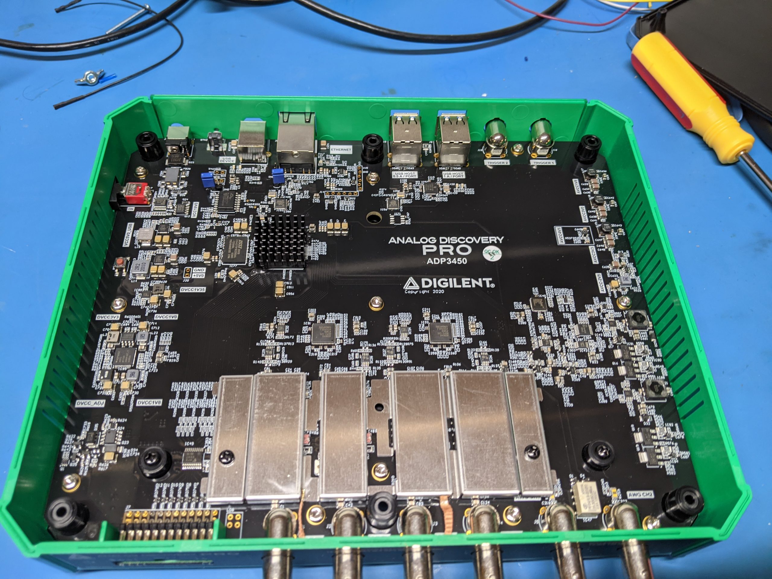
The upper left has a BGA with a heatsink on it – nothing too serious so a small Zynq maybe, or a helper FPGA? The power supplies and similar are all well labeled.
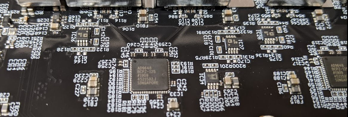
The ADC is a AD9648 – two of them on the 4-channel device. There are a few analog parts you can see, but a lot is hidden behind that metal shield:
Moving the metal shield up reveals it’s mostly just the relays for range switching:

Switching back to digital section, we can see the routing of the Digital IO goes to that BGA part, with DDR memory beside it:
Continue reading Analog Discover Pro TeardownHave you ever hand-built a PCB prototype with lots of parts? If so you’ll know the annoyance of hand-building something from a big stack of Digi-Key parts. Having to Ctrl-F the part value in the design, and dealing with hits on both top & bottom side. Instead I’m introducing Meat-Bag Pick-n-Place, which helps you the human meatbag become a PnP machine! Here’s a photo of it running:
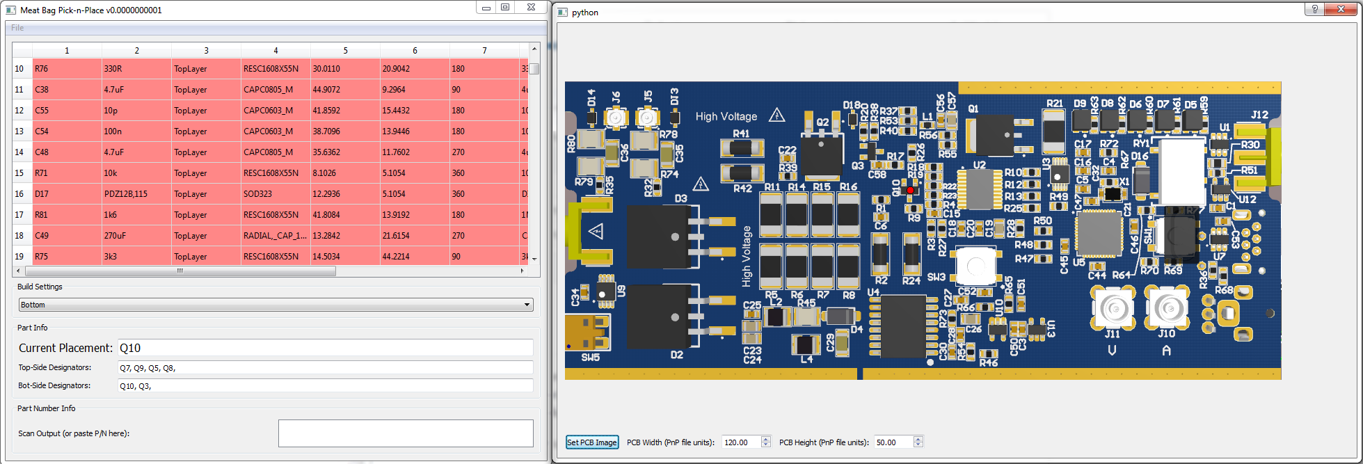
You can either click on an item, and it finds the first hit of it (i.e., click on a 200-ohm resistor) and shows you. You can then use spacebar to move through the placement list. It also interfaces to barcode scanners so you can just scan Mouser or Digikey bags. Here’s a short video demo:
All this is posted on the GitHub Repo, so hopefully you find it useful!
This summer, our summer intern Greg d’Eon made a quick project to build a X-Y Scanner from a 3D printer (by ‘quick’, I mean it took him less than 2 days!). You can see the source code up on GitHub. Anyway, 3D printers are very nice as they have fairly high resolution and fairly low cost. Here’s a quick video:
We’re using it to measure EM emissions frequencies over a PCB, but you could also use this for side-channel emissions, or fault injection. While the resolution might not be high enough for getting at specific features on a chip surface, it can still be used for general positioning.
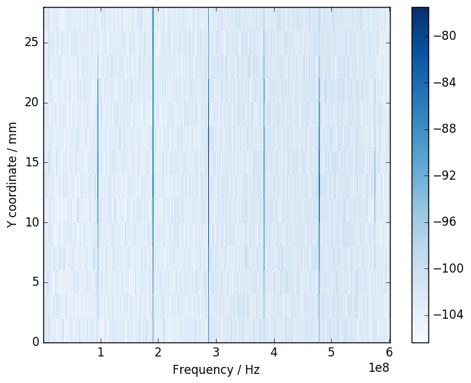
With your EM emissions, you can graph X-Y vs. amplitude – here I’ve constrained the range to get an idea where the 96 MHz emissions are concentrated. Probably more interesting would have been to use a 2D plot with colour overlaid over the PCB design: You can also do things like plot frequency vs. position with strength of the signal given by color. In the following graph the X position is fixed, and only the Y position is varied. You can see here the 96MHz oscillator of the SAM3U microcontroller on the ChipWhisperer-Lite for example:
The following blog post shows some details of my SMD soldering process. This was based on a larger video I did (linked below) showing the entire soldering process.
The following shows me soldering a complete board with BGA device.
In the above video, there are several pieces of equipment used. The following shows you some of the important ones.
I’m using a T962A reflow oven. I recommend this over the T962, which is a smaller version. The T962A has 3 heat lamps so has a more even heat distribution. Be aware you can’t use the full surface area – about the middle half I find is successful, but depends a little on complexity of the PCB.
I specifically purchased mine from this seller on AliExpress, check other sellers as prices change over time. You might turn it on quickly to confirm it works, but before doing much there are some important fixes:
I built a fume hood out of the following:
You can also improve one out of a range hood from an oven. See video for general fume hood construction.

This requires three things:
The tips are the only somewhat tricky thing. I had a good selection from a previous SMD picker tool, something like this kit for example (which is Chip Quick Inc. part #V8910). These tips are actually the same “Luer Lock” that fits into syringes, check E-Bay for cheaper kits:

You can also buy Chip Quik Inc part #VCS-9-B which has a bunch of these tips. It’s not the cheapest way, but if you are in a hurry will do! But all of these tips are for larger parts (i.e. maybe SOT23-3 at smallest). If you get into chip resistors, you need to go smaller.
For the small parts, you can bend “needle tips” slightly. You can buy packs of 50 from Digikey (search “Luer Lock”), but might find it cheaper to get individual ones from either medical supply places, or buying products which use them. For example some static-safe squeeze bottles come with a few tips. Again the expensive but easy route is Chip Quik part # SMDTA200 which has a bunch of different sized tips.

There is three main options for stencils:
For laser-cut stainless steel, this can typically be ordered with your PCB fab. For example 3PCB.com and Dirty PCBs offer them very cheaply (~$25) when ordering PCBs. This is almost always the best choice, as the stainless steel stencils are very reliable and I’ve had great success with BGA devices.
You can also use third-party services to cut Mylar or Kapton film for you. OSHStencils is one example of a supplier.
Finally, you can make your own. You’ll need some practice to cut BGA parts, but it’s quite easy to cut stencils for less demanding applications. I have a previous blog post on my method.
I’ve been making my own stencils with this process for some time with great success.
I purchased the squeegee from Dirty PCBs. There are some other blog posts on squeegee options you might look at.
I generally just buy solder past from Digikey. Digikey does a great job of cheaply shipping to Canada, and the paste comes in an awesome cold pack thingy that keeps it cool during the trip. Chip Quik (again with the Chip Quik sorry, I don’t have a connection with them but just end up using their stuff!) sells some nice small syringes. Be aware it does have a shelf life… I’ve used past about 6-12 months paste that date, but you will eventually see issues (balling, flux separates). I recommend keeping to the suggested date to avoid giving yourself the headache of discovering your paste is bad after you’ve tried soldering your PCB. The cost of all your parts is probably a lot more expensive than the cost of replacing your paste.
At ESC 2015 SV I gave a talk on using USB From Python, see the talk description here. This blog post is serving as a placeholder to allow me to update links to software used during the live demo.
For SuperCon 2015, there is a Project Page with these details too. You can also ask questions on the project page.
There is two versions of the slides. Use the SuperCon slides, but I left a copy of the ESC ones here in case you wanted the original for some reason.
Download Slides from Hackaday SuperCon 2015 (Newer Version for SAMD21) [PDF, 10MB]
Download Slides from ESC2015 (Older version for SAMD11) [PDF, 10MB]
For ESC I used a SAMD11 device, which needs a bit of a hack.
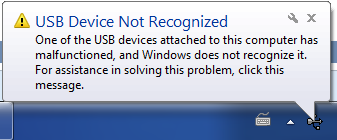
There is a bit of an “oopsie” in the SAMD11 devices. This bug isn’t in the official errata yet, and I’ve been told it’s limited to engineering sample devices (which were used in some of the early dev boards).
Basically the 48MHz oscillator calibration byte is wrong, and you need to manually tune this. You’ll know this problem exists as the device won’t be detected by Windows:
The work-around isn’t super-fun. First, use the programming interface to see the starting value of the DFLL48M_COARSE_CAL fuse:
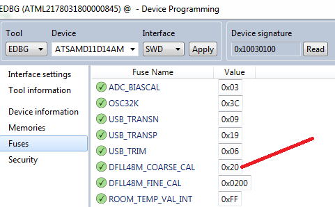
Next, search in the source code for reference to the dfll_conf.coarse_value variable. You will find where it is being setup, and you can override the value. Basically you have to experiment a bit to find a working value:

USB Test – Slide 87
import usb.core
dev = usb.core.find(idVendor=0x03eb, idProduct=0x2402)
print dev
If you get “None”, make sure you installed the “Filter Driver” using the LibUSB tools!
Control Endpoint Read – Slide 94
import usb.core
dev = usb.core.find(idVendor=0x03eb, idProduct=0x2402)
dev.set_configuration()

data = dev.ctrl_transfer(0b10100001, 0x01, 3<<8, 0, 4)

print data
If you get a “device is not functioning” error just skip this one…
Sending Output Report
import usb.core
dev = usb.core.find(idVendor=0x03eb, idProduct=0x2402)
print dev

dev.set_configuration()

data = [ord('1'), ord('1'), 0, 0, 0, 0, 0, 0]
dev.write(0x02, data)
Receiving Input Data (Press button to see change)
import usb.core
dev = usb.core.find(idVendor=0x03eb, idProduct=0x2402)
print dev

dev.set_configuration()

for i in range(0, 10):
    while True:
        try:
            test = dev.read(0x81, 8, timeout=50)
            break
        except usb.core.USBError, e:
            if str(e).find("timeout") >= 0:
                pass
            else:
                raise IOError("USB Error: %s"%str(e))

    print test
Full GUI Example
#Public domain - simple USB GUI Example by Colin O'Flynn

from PySide.QtCore import *
from PySide.QtGui import *
import usb.core
import sys

class USBForm(QDialog):
    def __init__(self, parent=None):
        super(USBForm, self).__init__(parent)
        self.setWindowTitle("ESC 2015 Demo")

        layout = QVBoxLayout()
        self.setLayout(layout)

        self.pbConnect = QPushButton("Connect")
        self.pbConnect.clicked.connect(self.con)
        self.isConnected = False

        self.pbLED = QPushButton("LED Blinking")
        self.pbLED.setCheckable(True)
        self.pbLED.clicked.connect(self.changeLED)
        self.pbLED.setEnabled(False)

        layout.addWidget(self.pbConnect)
        layout.addWidget(self.pbLED)

        self.swStatus = QLineEdit()
        self.swStatus.setReadOnly(True)
        layout.addWidget(self.swStatus)

        self.butTimer = QTimer(self)
        self.butTimer.timeout.connect(self.pollButton)


    def con(self):
        if self.isConnected == False:
            #Do USB Connect Here
            self.dev = usb.core.find(idVendor=0x03eb, idProduct=0x2402)
            self.dev.set_configuration()

            #Sync changeLED
            self.changeLED()

            self.isConnected = True
            self.pbConnect.setText("Disconnect")
            self.pbLED.setEnabled(True)
            self.butTimer.start(100)
        else:
            self.isConnected = False
            self.pbConnect.setText("Connect")
            self.pbLED.setEnabled(False)
            self.butTimer.stop()

    def changeLED(self):
        if self.pbLED.isChecked():
            #Send command to make LED on
            self.dev.write(0x02, [ord('1'), ord('1'), 0, 0, 0, 0, 0, 0])

            self.pbLED.setText("LED On")
        else:
            #Send command to make LED blink
            self.dev.write(0x02, [ord('0'), ord('1'), 0, 0, 0, 0, 0, 0])
            self.pbLED.setText("LED Blinking")

    def pollButton(self):
        try:
            data = self.dev.read(0x81, 8, timeout=50)
            if data[0]:
                self.swStatus.setText("Button Pressed")
            else:
                self.swStatus.setText("Button Released")

        except usb.core.USBError, e:
            if str(e).find("timeout") >= 0:
                pass
            else:
                raise IOError("USB Error: %s"%str(e))


if __name__ == "__main__":
    app = QApplication(sys.argv)
    form = USBForm()
    form.show()
    sys.exit(app.exec_())
A while back I got a Seek thermal camera, as I wanted to use it for measuring electronics component temperatures. As part of a course I’m teaching at Dal, I did a few experiments I wanted to post here. These photos were taken with a macro lense, shown here:

To get that lens, I purchased a 20mm diameter ZnSe Lens with 50.8mm/2″ focus off E-Bay for about $20. I ended up getting both a 100mm and 50mm focal length to try both. Then you need a holder, which I used one I found on Thingiverse. If printing again I’d try to enlarge the size of the space for the lens – I had to use a knife and considerably carve the inside step down. In fact I’d remove the middle ‘ridge’ which holds the lens in, and instead epoxy it.
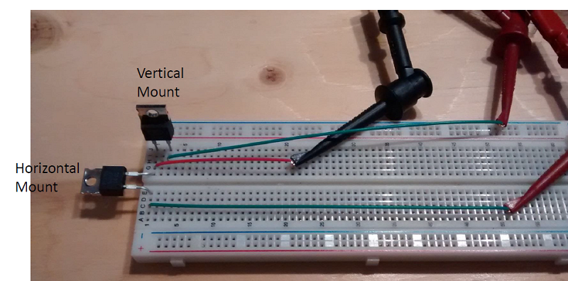
I’m using a TO-220 5 ohm resistor, which lets me reliably control the power being dissipated by the device. The part number is PF2205-5R which you can get at Digikey.
The first test compares mounting the resistor horizontally and vertically. To do this I’ve put two into a breadboard:
Which we power with constant power using my supply:
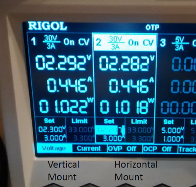 And can see the difference in temperature between the two:
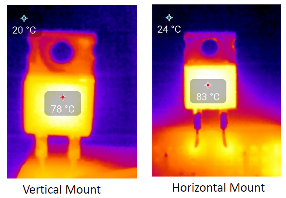
So what gives? There is (expected) to be two reasons for the temperature difference:
The majority of this comes from #1, but people will complain if I don’t mentioned #2. If your heatsinks has lots of fins, it’s worthwhile to ensure the natural airflow due to heat easily flows up the heatsink.
Also note the temperature rise is about what is expected of a TO220 package, which typically has about a 62ºC/W Junction to Case thermal resistance. Ambient is around 20C, so with 1W of power in we expect 20ºC + 62ºC = 82ºC case temperature. Cool!
The second test tries several mounting of TO220 packages on a PCB. The PCB setup is shown here:
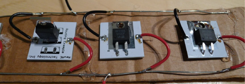
First, let’s look at the vertically mounted device. Here is the thermal image once it reaches steady-state:

What the hell happened? We still had 1W of input per transistor, but it’s 14C cooler than the other test!
In this case the PCB is dissipating some of the heat – the entire top and bottom are solid copper pours, each side connected to one of the pins. This is almost idea for heat transfer.
Next, let’s look at the other two resistors. The following shows both details of the mounting and the steady-state temperatures:
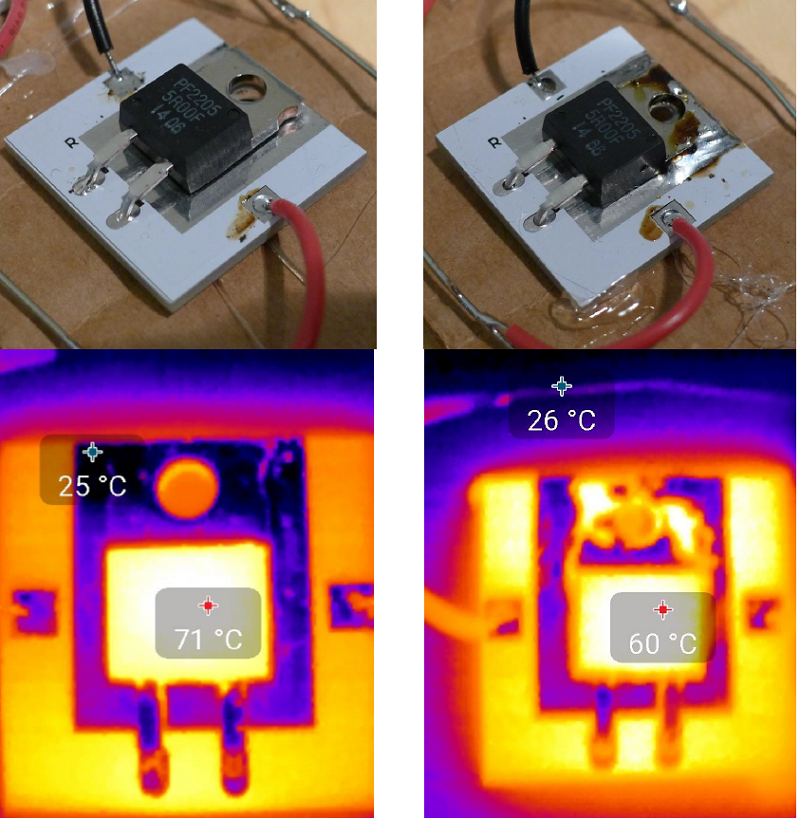 I should mention the reflection areas have low thermal emissivity, and the Seek camera doesn’t pick them up correctly. Thus the tab & PCB area without solder-mask aren’t actually cooler.
Anyway you can see that mounting the package *close* to a good heatsink but without actually touching it is worse than free-space mounting. Having a good connection (in this case soldering) as expected further reduces the case temperature by allowing the PCB to dissipate more of the heat.
The “close but not touching” comes up a lot – for example if you make a simple metal shield for your device, you might think it a good idea to have the shield come close to heat-producing devices. But unless it actually makes good contact, you are probably hampering the natural convection air currents!
When I get some more time I plan on buying a few different heatsinks from Digikey and compare my measured temperature rise with the theoretical temperature rise.
The USB spec has limits on the ‘inrush current’, which is designed to prevent you from having 2000uF of capacitance that must be suddenly charged when your board is plugged into the USB port.
The limit works out to around 10uF of capacitance . Your board might have much much more – so you’ll have to switch portions of your board on later with FETs as a soft-start.
For the ChipWhisperer-Lite, I naturally switch the FPGA + analog circuitry as to meet the 2.5 mA suspend current. Thus I only have to ensure the 3.3V supply for the SAM3U2C meets the inrush limits, which is a fairly easy task. This blog post describes how I did this testing.
The official USB Test Specs for inrush current testing describe the use of the Tektronix TCP202 which is $2000, and I don’t think I’d use again a lot. Thus I’m describing my cheaper/easier method.
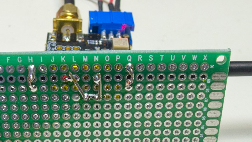
First, I used a differential probe (part of the ChipWhisperer project, so you can see schematics) to measure the current across a 0.22 ohm shunt resistor. The value was selected as I happened to have one around… you might want a smaller value (0.1 ohm say) even, as the voltage drop across this will reduce the voltage to your device. The differential probe has enough gain to give your scope a fairly clean signal. This shows my test board, where the differential probe is plugged into a simple 2-pin header:
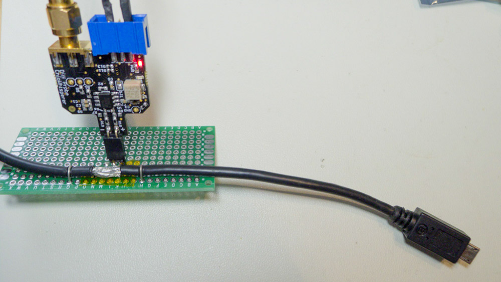
From the bottom, you can see where I cut the USB shield to bring the +5V line through the shunt:
To calibrate the shunt + gain from the diff-probe, I just used some test loads, where I measure the current flowing through them with a DMM. You can then figure out the equation for converting the scope measurement to a current in amps.
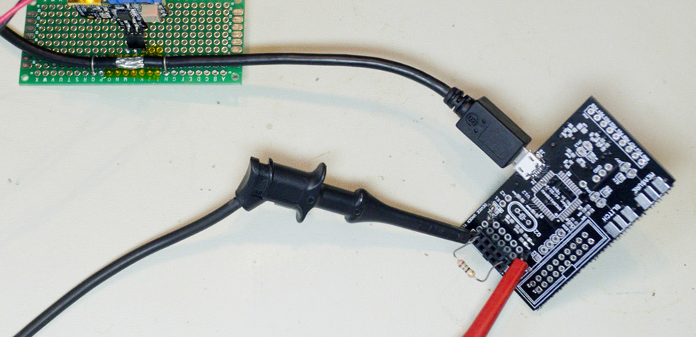
Finally, we plug in our actual board. Here I’ve plugged in the ChipWhisperer-Lite prototype. The following figure shows the measurement after I’ve used a math channel in PicoScope to convert the voltage to a current measurement, and I’ve annotated where some of these spikes come from:
Saving the data, we can run through the USB Electrical Analysis Tool 2.0 to get a test result. The USB-IF tool assumes your scope saves the files with time in seconds and current in amps. The PicoScope .csv files have time in miliseconds, so you need to import the file into Excel, divide the column by 1000, and save the file again. Finally you should get something like this:

Note the inrush charge is > 50mC, but there is an automatic waiver for anything < 150 mC. While the system would be OK due to the waiver, I would prefer to avoid exceeding the 50 mC limit. In this case there’s an easy solution – I can delay the USB enumeration slightly from processor power-on, which limits the inrush to only the charging of the capacitors (which is done by ~15mS). This results in about 47 mC. This means I’ve got about 100 mC of headroom before I exceed the official limits!
This extra headroom is needed in case of differences due to my use of the shunt for example.
In addition, I should be adjusting the soft-start FET gate resistor to reduce the size of that huge soft-start spike. Ideally the capacitor charging shouldn’t draw more than the 500mA I claim when I enumerate, so that’s a little out of spec as-is! If I don’t want to change hardware I could consider using PWM on the FET gate even…
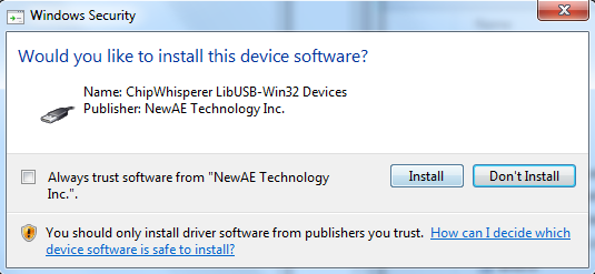
I recently wanted to sign some drivers to avoid requiring users of my ChipWhisperer device to do the usual bypass-signature deal. The end result is a sweet sweet screen like this when install the drivers:
If you are in this situation, I wanted to add some of my own notes into the mix.
David Grayson has an awesome guide which I mostly followed, available at http://www.davidegrayson.com/signing.
The steps I followed (again from his guide basically) are:
"C:\Program Files (x86)\Windows Kits\8.1\bin\x86\inf2cat" /v /driver:%~dp0 /os:XP_X86,Vista_X86,Vista_X64,7_X86,7_X64,8_X86,8_X64,6_3_X86,6_3_X64
"C:\Program Files (x86)\Windows Kits\8.1\bin\x86\signtool" sign /v /n "Your Company Name Inc." /tr http://timestamp.globalsign.com/scripts/timestamp.dll *.cat
"C:\Program Files (x86)\Windows Kits\8.1\bin\x86\signtool" sign /v /n "Your Company Name Inc." /tr http://timestamp.globalsign.com/scripts/timestamp.dll /fd SHA256 /as *.cat
pause
The batch file I use above signs both a SHA1 and SHA256 signature. SHA1 is being deprecated due to collision attacks (interesting sidenote: these were used as part of the attack on Iranian centrifuges by creating digitally signed drivers).
Unfortunately SHA256 isn’t fully supported across all platforms you might need to support (see https://support.globalsign.com/customer/portal/articles/1499561-sha-256-compatibility), so for now I’m using both, which I think works?
I made some additional details in a long YouTube movie:
This is far from the first blog post on this, but I wanted to write down exactly what I did to get this working on Windows 7, 64-bit with as little fussing as possible.
2. Decide on material. I originally used the Transparency Film but it’s a little thick, so instead ended up finding that you can buy 3 Mil drafting file individually from art stores.
3. Install USB drivers from CD that came with system – this seems to be required, as installing the software from the website alone wasn’t enough. If you need them I’ve mirrored a copy here: silhoutte_cameo_drivers.
4. Plug in Cameo device. Check if it appears as a printer:
If it DOES NOT, screw around with drivers. For me it appeared as “USB Printer Support” for a while, you’ve got to try updating the drivers and forcing it to use the ones from the CD it seems. Eventually you should have success.
5. Share the Cameo device under “Printer Properties”:
6. Install gerbv
7. Install pstoedit 64-bit or pstoedit 32-bit as appropriate
8. Install Ghostscript 64-bit or Ghostscript 32-bit as appropriate
9. Download copy of gerber2graphtec repo, unzip it somewhere. I’ve linked to my fork of the repo which contains some extra stuff, so if you want the original check the gerber2graphtec pmonta repo
10. Run the GUI. You’ll need to modify paths probably, or at least version numbers. Set the folder share option to match your computer name / printer share:
11. If you haven’t loaded the Cameo before, basically check out the booklet that came with it. Set the cutting depth to ‘1’ on the blade and shove it into the machine. Peel back the blue sheet off the ‘cutting mat’, and stick the transparency to the mat.
12. Load a test gerber, convert it (check the output of the command line doesn’t have errors), and send onward! For me things ‘just worked’.
13. You can use the generate test square feature I added to generated the test pattern. Forces increase from 1 to 30 as it draws the squares.