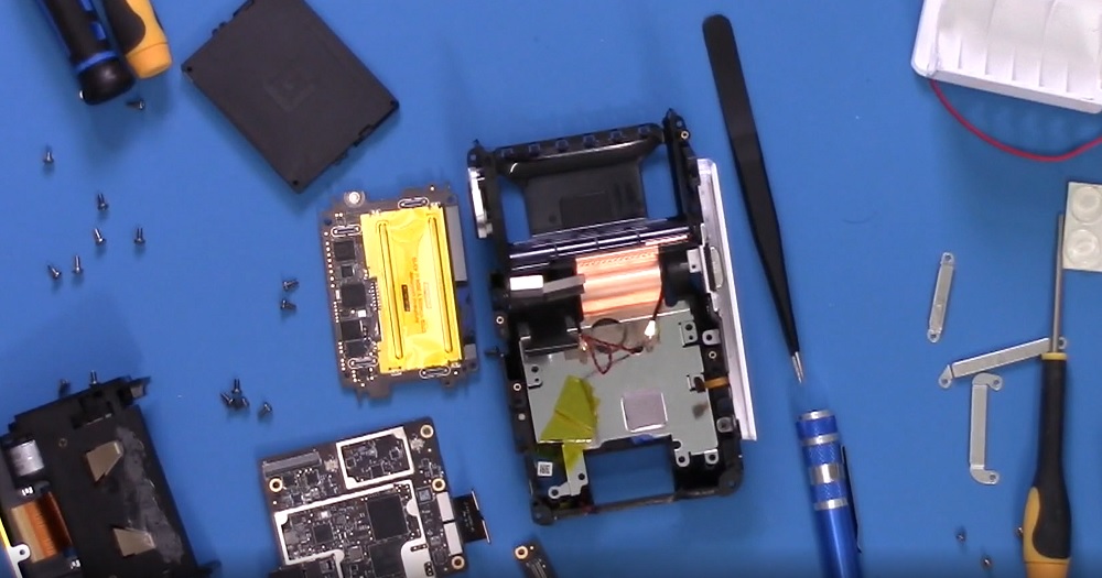
I recently tore down a square terminal (the one with the LCD screen) and wanted to share some of these results. I haven’t photographed everything as was mostly interested in how the secure areas of it are down. You can see an overview in the following video if you want to see how the whole thing fits together.
You can pull the main boards out to boot the thing on your bench (WARNING: as you see in the video above, this will trip the tamper circuits and destroy the device from being able to register/use):
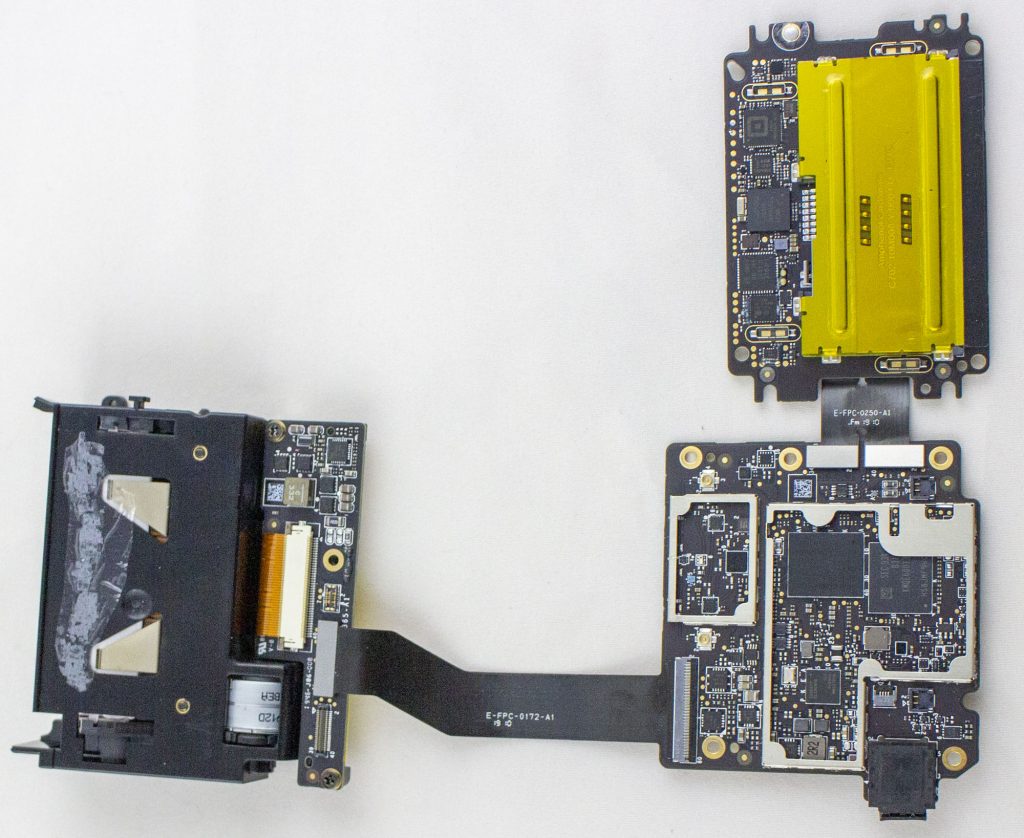
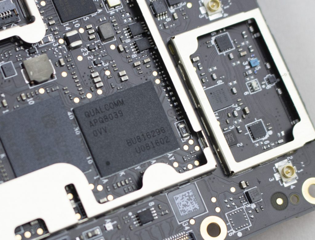
To start with the boring, here is the android board. It uses an APQ8039 (SnapDragon 615) as the main processor, with a KMQE60013M-B318 which integrates NAND (Emmc) and LPDDR in one package.
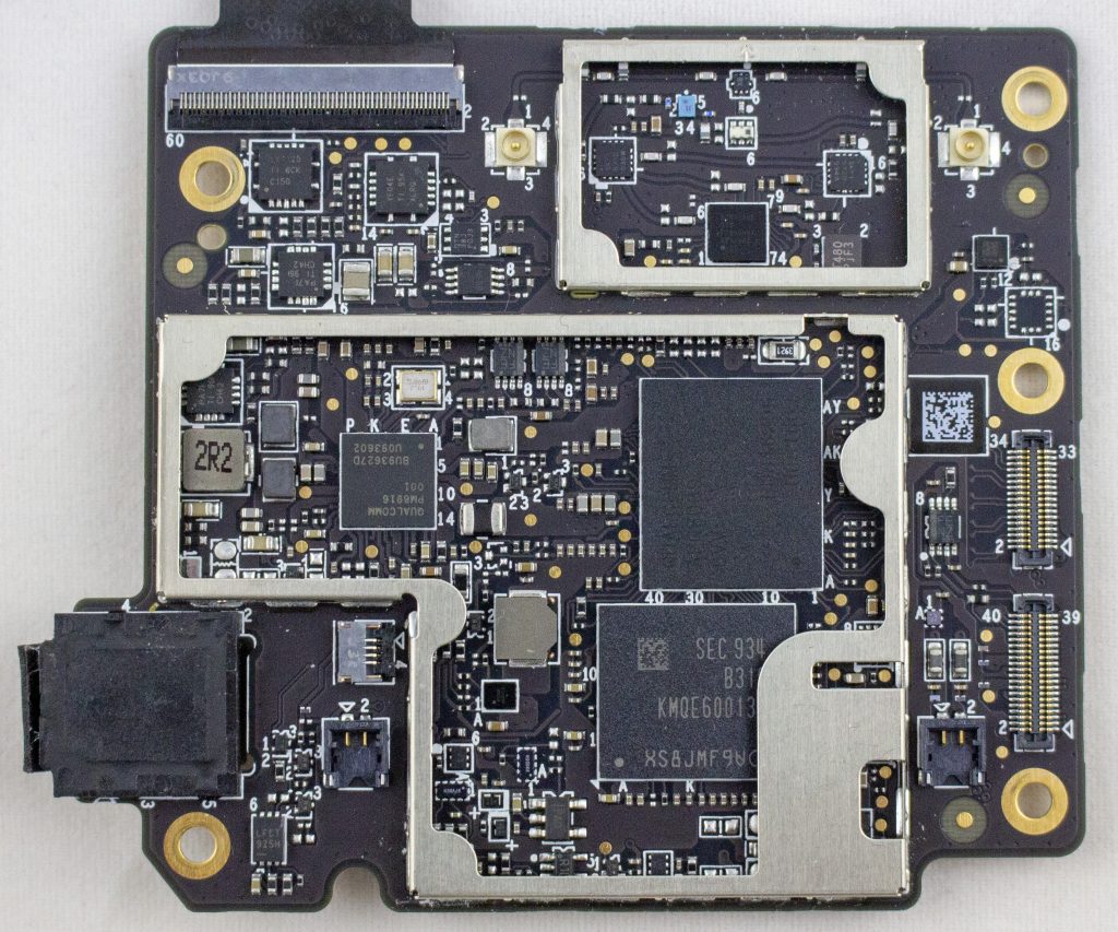
Alright, cool enough? While let’s get into the main stuff. There is a “security board” which I talk about in the following video:
This board features: MK21FX512 main microcontroller, a TDA9034 smartcard interface, a “Square K400Q”, a Cirque ICA037 touch controller, STM32F0, TS3A44159RGTR (analog mux), Lattice ICE5LP2K FPGA. Here’s a photo of the board with the taper screen removed:
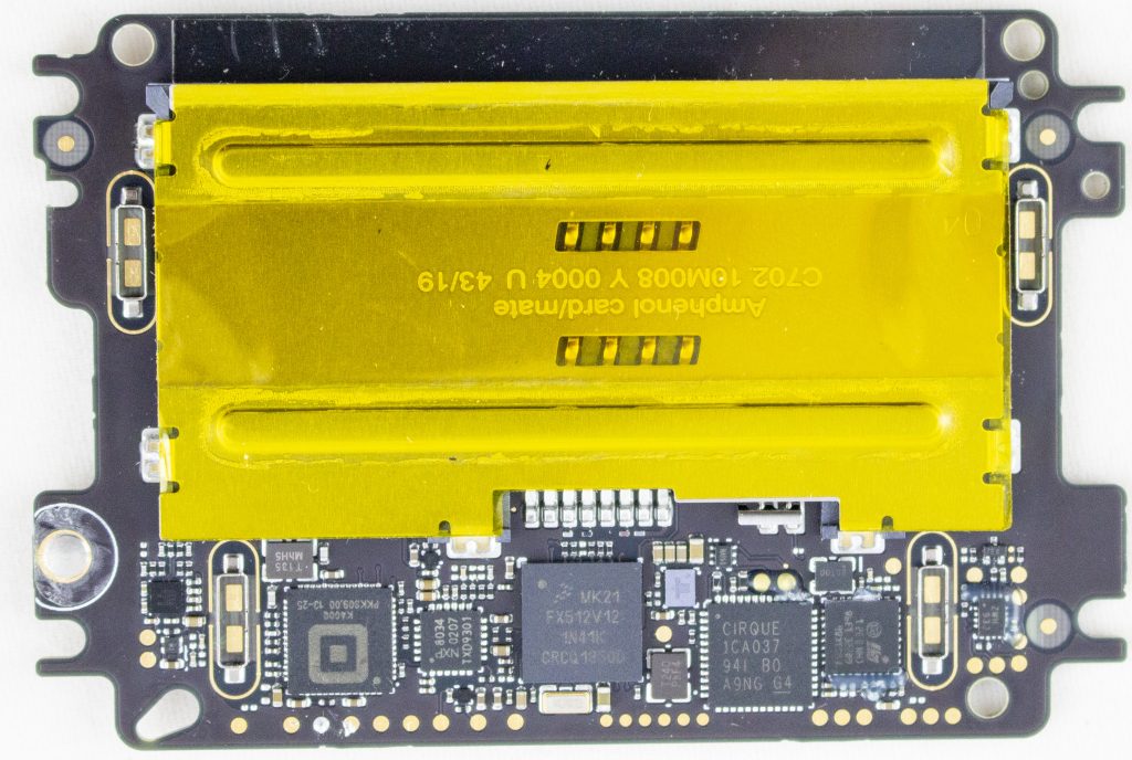
The tamper shield covers all of those test pads. Here’s a photo of the tamper screen:
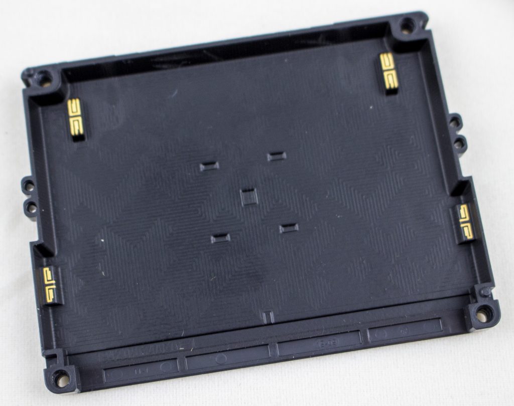
Very conveniently (for us), Square has filed a number of patents related to the tamper. In particular, here and here feature this exact cover:

I had measured out the connections, but the patent itself detailed them:

They patent also explains the land patterns on the PCB. The extra rings around it are for guard rings – if someone were to squirt some conductive glue into the enclosure, they would also trip the guard ring. Cool!

The other question of what is the Square K400Q device, which has a 13.56 MHz crystal hanging off it? While it turns out Square acquired a company called Kili Technology. And Kili Technology had a product called the K400Q, which is also in QFN-56 package. You can find the product page here (thanks to archive.org). No full datasheet, but it does have a short product brief:
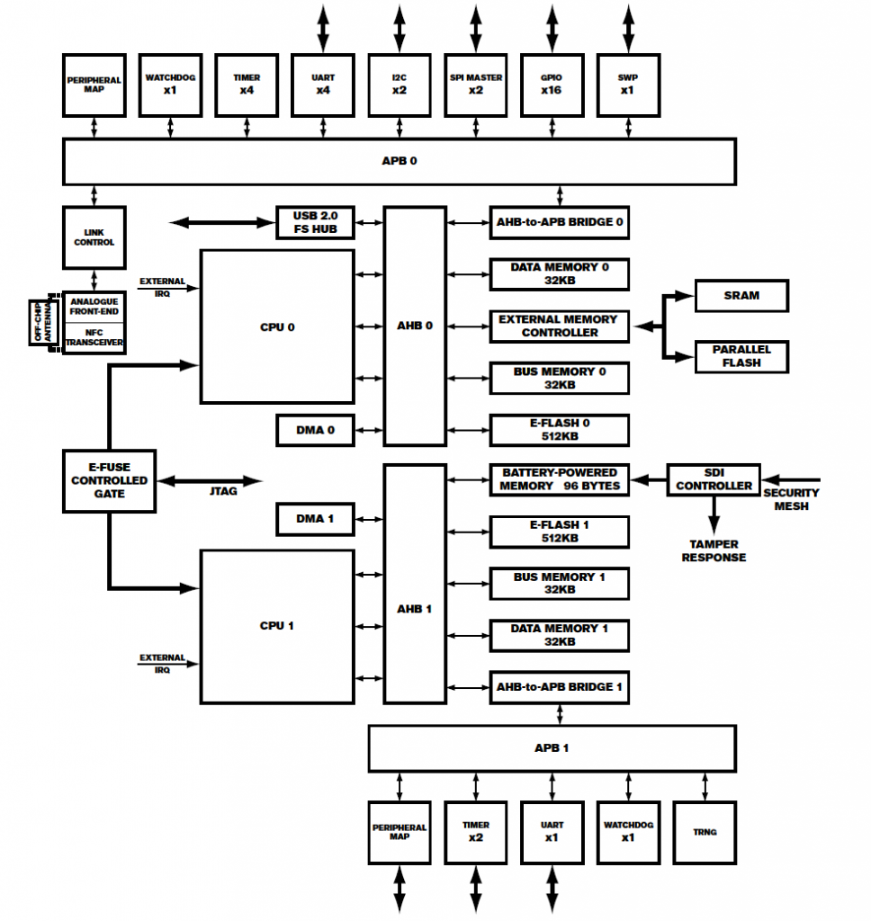
What else is in it? Unclear exactly, but I would bet it’s using an enSilica RISC processor based on this press release. Unfortunately there aren’t public tools for it, although Lauterbach supports it in some form.
Finally – where is that security mesh handled? In my video I trace out some of it – the backup battery seems to run across the mesh on one side. The otherside seems to route to the STM32F0 processor. So it might be that the STM32F0 is performing some of the security mesh checking, which then triggers the Secure Destroy Interface (SDI) on the Square K400Q microcontroller. The STM32F0 has some epoxy blocking a few pins (very suspicious) as does the analog mux. The analog mux has some interesting-looking signals on it that make me suspect it is also part of the security mesh.
As a small side-note: all those test pads are right at the edge of the mesh. I haven’t tested yet, but I’m curious if you can dig down ‘under’ the shield without tripping anything. Or a very very fine shim may fit between the PCB & shield perhaps. Lots of stuff to test!
But that’s all for now. Project has been shelved for a bit, but hopefully you enjoy this look into the Square teardown!
MINOR UPDATE: I removed the epoxy around the STM32F0 – it looks like it might be near the mesh, but the mesh isn’t actually routing to the STM32F0 inputs (not 100% clear yet). The mesh seems to power the backup power for the MK21 instead, so it’s clear more effort is needed. Next step will be to remove the BGA on the MK21 so can probe where the mesh is going exactly.