I recently tore down a square terminal (the one with the LCD screen) and wanted to share some of these results. I haven’t photographed everything as was mostly interested in how the secure areas of it are down. You can see an overview in the following video if you want to see how the whole thing fits together.
Teardown of Square Terminal Video
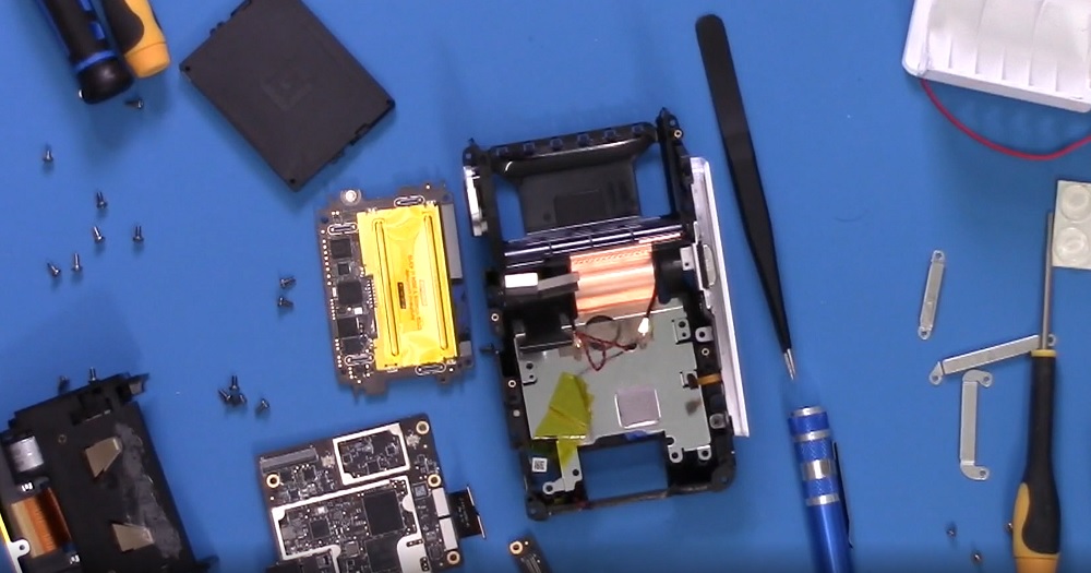
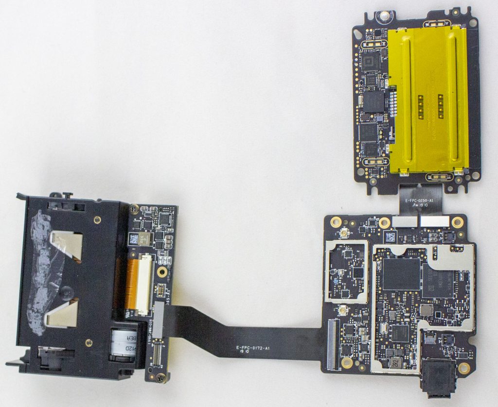
You can pull the main boards out to boot the thing on your bench (WARNING: as you see in the video above, this will trip the tamper circuits and destroy the device from being able to register/use):
Benching the boards – tamper shield removed from secure device (more on that later).
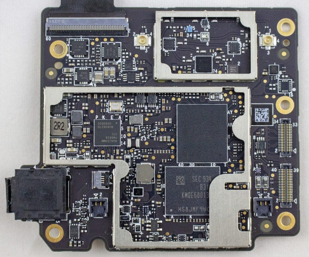
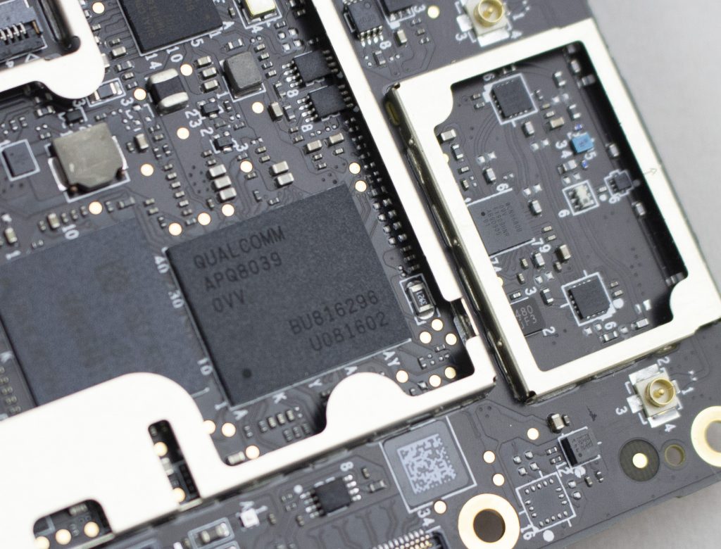
To start with the boring, here is the android board. It uses an APQ8039 (SnapDragon 615) as the main processor, with a KMQE60013M-B318 which integrates NAND (Emmc) and LPDDR in one package.
Alright, cool enough? While let’s get into the main stuff. There is a “security board” which I talk about in the following video:
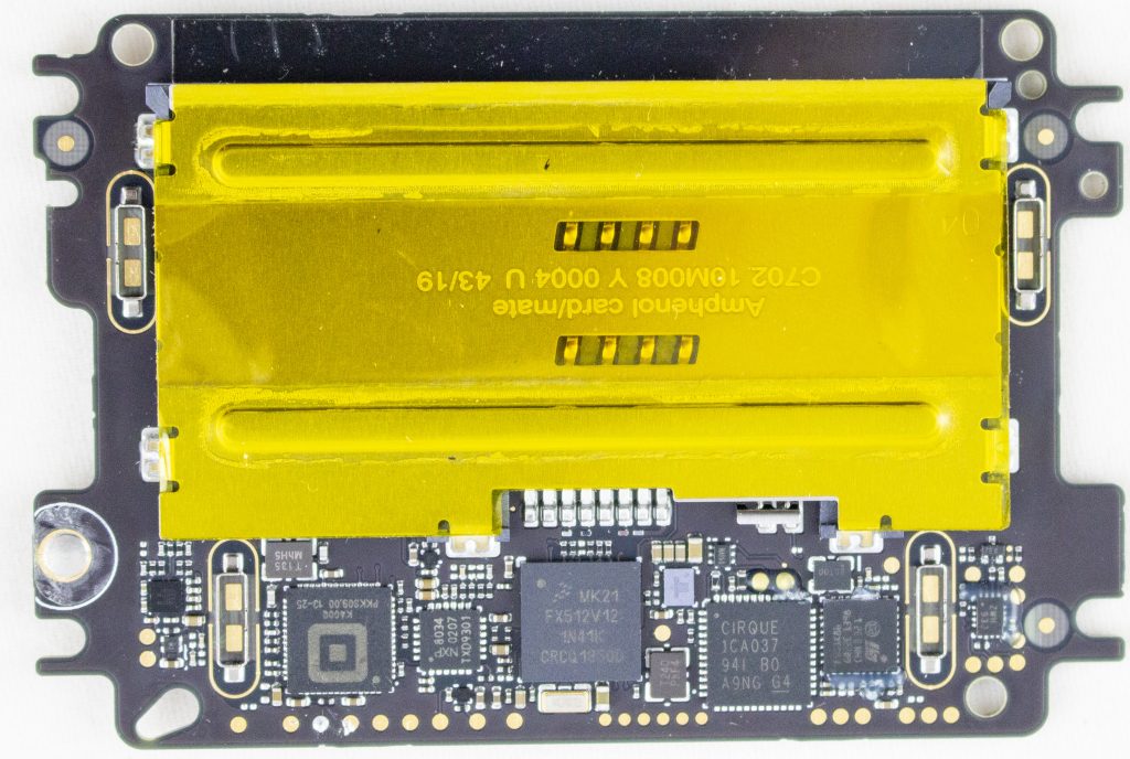
This board features: MK21FX512 main microcontroller, a TDA9034 smartcard interface, a “Square K400Q”, a Cirque ICA037 touch controller, STM32F0, TS3A44159RGTR (analog mux), Lattice ICE5LP2K FPGA. Here’s a photo of the board with the taper screen removed:
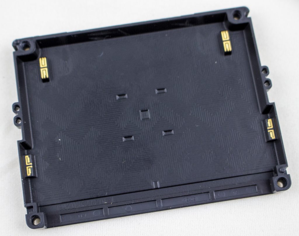
The tamper shield covers all of those test pads. Here’s a photo of the tamper screen:
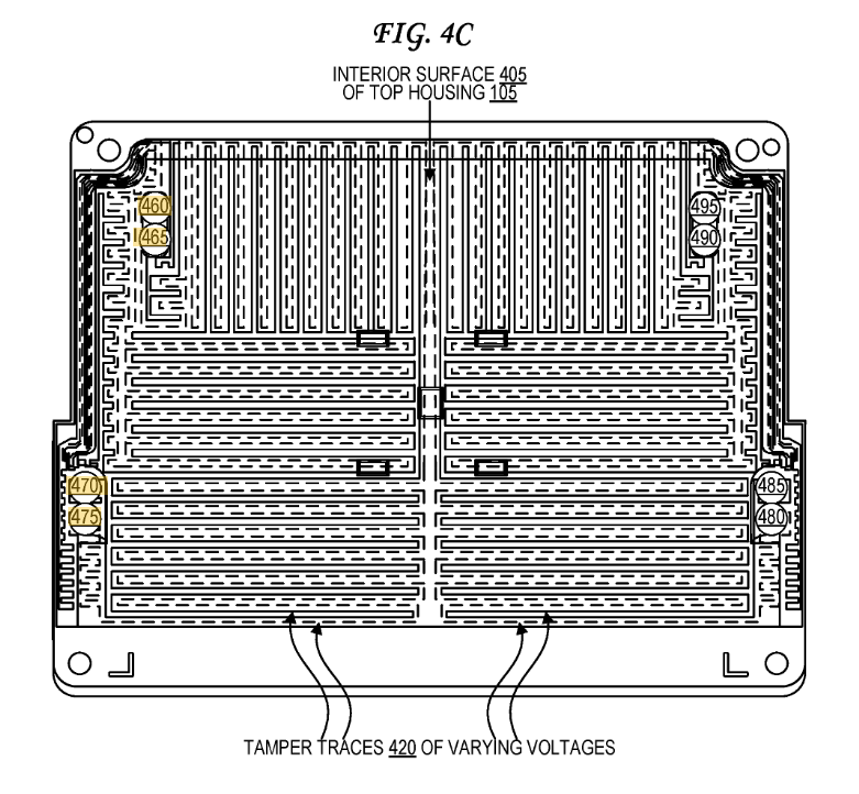
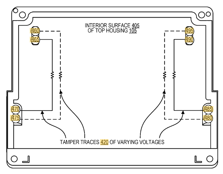
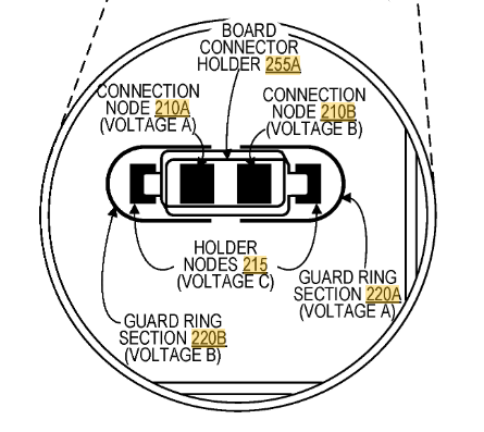
Very conveniently (for us), Square has filed a number of patents related to the tamper. In particular, here and here feature this exact cover:
I had measured out the connections, but the patent itself detailed them:
They patent also explains the land patterns on the PCB. The extra rings around it are for guard rings – if someone were to squirt some conductive glue into the enclosure, they would also trip the guard ring. Cool!
The other question of what is the Square K400Q device, which has a 13.56 MHz crystal hanging off it? While it turns out Square acquired a company called Kili Technology. And Kili Technology had a product called the K400Q, which is also in QFN-56 package. You can find the product page here (thanks to archive.org). No full datasheet, but it does have a short product brief:
What else is in it? Unclear exactly, but I would bet it’s using an enSilica RISC processor based on this press release. Unfortunately there aren’t public tools for it, although Lauterbach supports it in some form.
Finally – where is that security mesh handled? In my video I trace out some of it – the backup battery seems to run across the mesh on one side. The otherside seems to route to the STM32F0 processor. So it might be that the STM32F0 is performing some of the security mesh checking, which then triggers the Secure Destroy Interface (SDI) on the Square K400Q microcontroller. The STM32F0 has some epoxy blocking a few pins (very suspicious) as does the analog mux. The analog mux has some interesting-looking signals on it that make me suspect it is also part of the security mesh.
As a small side-note: all those test pads are right at the edge of the mesh. I haven’t tested yet, but I’m curious if you can dig down ‘under’ the shield without tripping anything. Or a very very fine shim may fit between the PCB & shield perhaps. Lots of stuff to test!
But that’s all for now. Project has been shelved for a bit, but hopefully you enjoy this look into the Square teardown!
MINOR UPDATE: I removed the epoxy around the STM32F0 – it looks like it might be near the mesh, but the mesh isn’t actually routing to the STM32F0 inputs (not 100% clear yet). The mesh seems to power the backup power for the MK21 instead, so it’s clear more effort is needed. Next step will be to remove the BGA on the MK21 so can probe where the mesh is going exactly.
Have you been interested in the Echo Dot device? One feature they mention is that there is a microphone off button. I spent a few hours reverse engineering this, and recorded (in un-edited glory) the process:
The resulting schematic is shown below:
The astute reader will note the only pin under direct control allows the disabling of the microphone, it cannot re-enable it. However – there is one more loophole to check.
The microphone comes up in an “online” state due to the strapping circuit. On quick check, it appears the 3.3V source is coming directly from a main 3.3V regulator which doesn’t seem to be controlled by the microcontroller. But I don’t guarantee there isn’t some way for the microcontroller to turn off the entire power, which if so would cause the microphone to be re-enabled when the device turns back on. It’s the last thing I’ll investigate, but will take some more effort to do so.
At CHES 2019 [rump session], I presented my revolutionary talk on Time Travel Resistant Cryptography (TTRC). This is a hugely important area of research that has been widely ignored in academic work, and it’s time to finally make this right.
Why is this so critical? While Post Quantum Cryptography (PQC) gets NIST contests, and invested companies, nobody is considering TTRC. The general thought-process of PQC is that the existence of sufficiently powerful quantum computers is an open problem with no clear solution. BUT – if someone solves that problem (that is unclear is even physically possible to solve), it’s going to be hell on Earth for crypto implementations. Better safe than sorry.
That sounds a hell of a lot like some other problems to me.
And that problem even have had multiple movies made about it:
Lots of open questions exist. But note that many of them are not so unreasonable. For example – what if time travel requires us to create a Closed Timelike Curve (CTC), and time travel is only possible from the point that curve is created and onward.
This would mean that from the point the CTC is created crypto would immediately be broken, but any point before that (i.e., now) is safe. Thus we must create TTRC implementations since we cannot know when CTCs could be created.
I discuss many of these problems in my CHES 2019 Rump Presentation, you can see the slides below. When video is posted I’ll update this blog post with such material.
This blog post covers several topics that I should have made independent posts about… but anyway. Here we are. It’s September and I should have done this months ago.
Trezor / USB Hacking Updates (Black Hat + WOOT)
I had an earlier blog post with details of the Trezor attack. It turns out this is more generic type of attack than I realized, so I extended this work into a WOOT paper as well. Quickly I thought I should update on that…
This paper includes some additional details. One major thing is that the USB attack I used in the Trezor applies to many other devices. Basically almost everything has something like the following chunk of code:
if (∗length > setup−>wLength) {
   ∗length = setup−>wLength;
}
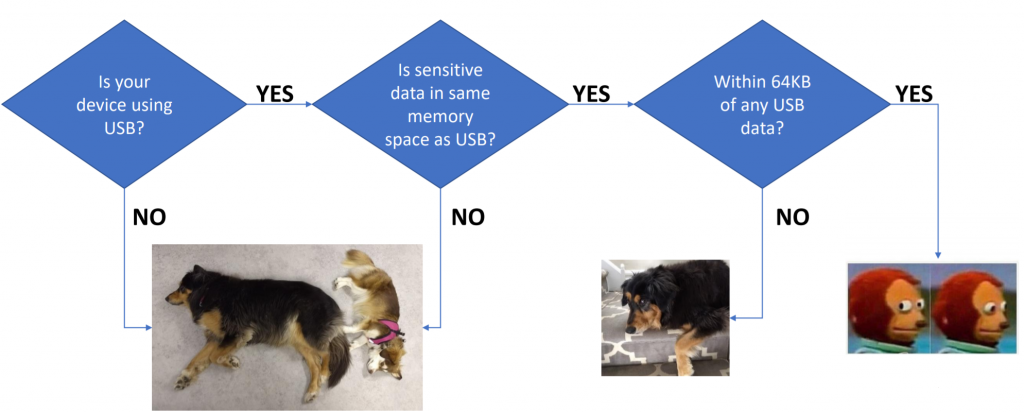
The problem comes about because the wLength field ends up coming from the computer (host). Using fault injection we can always cause that code-path to be taken, meaning we can read out data directly from the target device. This applies in only certain circumstances… here is a quick flow-chart of when you should care:
As mentioned on the Trezor blog post, their latest security patch fixes a flaw I disclosed to them in Jan 2019. This flaw meant an attacker with physical access to the wallet can find the recovery seed stored in FLASH, and leave no evidence of tampering.
This work was heavily inspired by the wallet.fail disclosure – I’m directly dumping FLASH instead of forcing the flash erase then dumping from SRAM, so the results are the same but with a different path. It also has the same limitations – if you used a password protected recovery seed you can’t dump that.
Practically, it has the advantage of not requiring you to modify/tamper with the enclosure at all either to do the fault injection or read data off . Wallet.fail uses the physical JTAG connection, whereas I’m using the USB connection. But by comparison the wallet.fail attack is more robust and easier to apply – my EMFI attack can be fiddly to setup, and there is some inherent timing jitter due to the USB stack processing. Without further effort to speed up my attack, it’s likely the process of opening the enclosure & applying the wallet.fail method would be a faster in practice.
Please do not contact me if you have a “forgotten password” or something similar with your Trezor. I’m not willing to perform this work under any circumstances.
Summary
USB requests that read from memory (such as a USB descriptor read) accept a maximum packet size that is MIN(requested_size, size_of_data_structure). The code as written defaults to accepting the requested size, and overwriting it with a smaller “valid” value.
Using fault injection (here demo’d with EMFI), this check
can be skipped. The device will accept up to 0xFFFF as a size argument, giving
an attacker access to read large chunks of either SRAM or FLASH (depending
where the descriptor is stored).
Due to the FLASH memory layout, the sensitive metadata lies
roughly AFTER the descriptors stored in bootloader flash space. Thus an
attacker can read out the metadata structure from memory (seed etc). Notably
this does not require one to open
the enclosure due to use of EMFI.
Using voltage glitching would almost certainly work as well, but likely requires opening the enclosure making tampering more evident (possibly it would work via USB +5V input even which wouldn’t require opening the enclosure).
Details
I’ve chosen to demo this with WinUSB descriptor requests, as
they have a very simple structure. In addition the WinUSB has one descriptor in
FLASH and one in SRAM, giving you the ability to chose which memory segment to
dump. Other USB requests should work too, but I haven’t tested them.
Consider the following function, where the critical calls are the len = MIN(len,…) calls (two of them can be found):
static int winusb_control_vendor_request(usbd_device *usbd_dev,
					struct usb_setup_data *req,
					uint8_t **buf, uint16_t *len,
					usbd_control_complete_callback* complete) {
	(void)complete;
	(void)usbd_dev;

	if (req->bRequest != WINUSB_MS_VENDOR_CODE) {
		return USBD_REQ_NEXT_CALLBACK;
	}

	int status = USBD_REQ_NOTSUPP;
	if (((req->bmRequestType & USB_REQ_TYPE_RECIPIENT) == USB_REQ_TYPE_DEVICE) &&
		(req->wIndex == WINUSB_REQ_GET_COMPATIBLE_ID_FEATURE_DESCRIPTOR)) {
		*buf = (uint8_t*)(&winusb_wcid);
		*len = MIN(*len, winusb_wcid.header.dwLength);
		status = USBD_REQ_HANDLED;

	} else if (((req->bmRequestType & USB_REQ_TYPE_RECIPIENT) == USB_REQ_TYPE_INTERFACE) &&
		(req->wIndex == WINUSB_REQ_GET_EXTENDED_PROPERTIES_OS_FEATURE_DESCRIPTOR) &&
		(usb_descriptor_index(req->wValue) == winusb_wcid.functions[0].bInterfaceNumber)) {

		*buf = (uint8_t*)(&guid);
		*len = MIN(*len, guid.header.dwLength);
		status = USBD_REQ_HANDLED;

	} else {
		status = USBD_REQ_NOTSUPP;
	}

	return status;
}
We can see from disassembly this is a simple comparison to the maximum size. I’m mostly going to be looking at the guid structure since it’s located in FLASH below the metadata. Glitching the code in the red box below would create our required vulnerability:
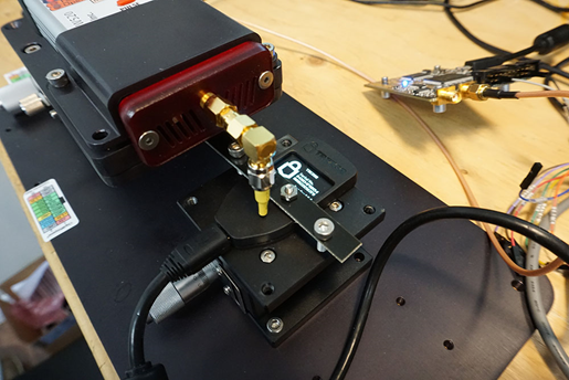
The glitch is inserted with a ChipSHOUTER EMFI tool. The Trezor is held in bootloader mode with two spacers on the buttons, and the EMFI tool is positioned above the case, as shown below:
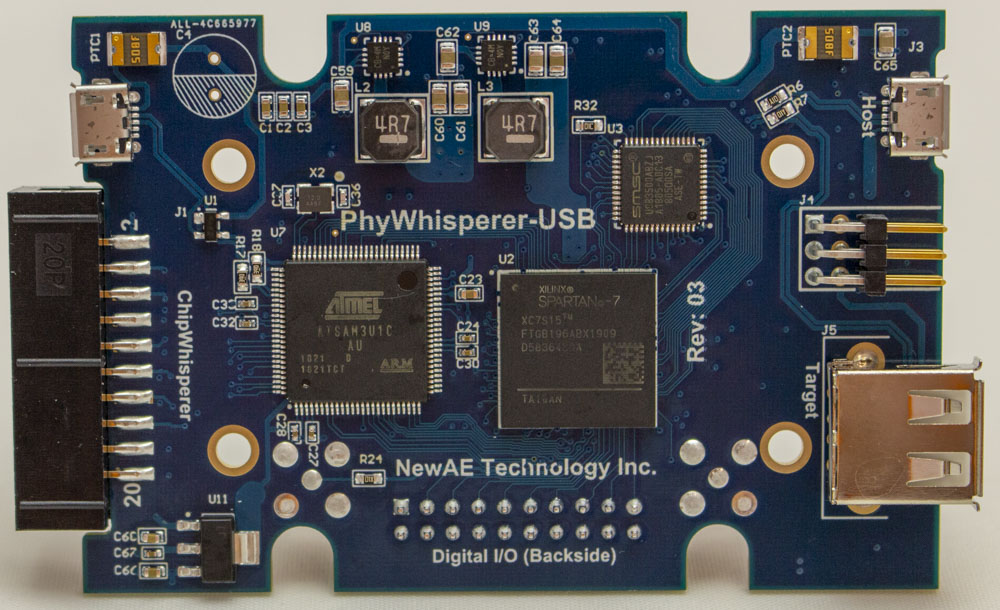
The entire setup is shown below, which has the ChipSHOUTER
(bottom left), a ChipWhisperer-Lite (top left) for trigger delay, a Beagle 480
for USB sniffing/triggering (top center) and a switchable USB hub to
power-cycle the Trezor when the EMFI triggers the various hard fault/stack
smashing/memory corruption errors (top right).
The forced bootloader entry mode simplifies the glitch, as we can freely power cycle the device and try many glitches.
A glitch is timed based on a Total Phase USB analyzer. The USB request is sent from a host computer as shown below:
def get_winusb(dev, scope):
    """WinUSB Request is most useful for glitch attack"""
    scope.io.glitch_lp = True #Enable glitch (actual trigger comes from Total Phase USB Analyzer)
    scope.arm()
    resp = dev.ctrl_transfer(int('11000001', 2), ord('!'), 0x0, 0x05, 0xFFFF, timeout=1)
    resp = list(resp)
    scope.io.glitch_lp = False #Disable glitch
    return resp
This corresponds to reading the “guid”. The Beagle480 is setup to generate a trigger on the first two bytes of this request:
To confirm the timing, I also compiled my own bootloader,
and saw the sensitive operation was typically occurring in the 4.2 to 5.7uS
after the Beagle480 trigger. There was some jitter due to the USB stack
processing.
A ChipWhisperer-Lite is used to then generate a 4.4uS offset
(empirically a good “waiting” place), after which an EMFI pulse is triggered.
Should the 4.4uS offset happen to line up with the length checking/limiting, we
can get a successful glitch.
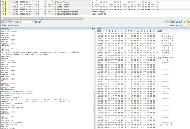
A successful glitch will return much more data than expected – possibly up to the full 0xFFFF, but because things are getting corrupted it sometimes seems to be less. Also some OSes limited the maximum size you can request -you can find some references to that on the libusb mailing list. As a first step you might just try 0x1FF or something (anything larger than the correct 0x92 response). But here is a screen-shot showing three correct transfers (146 bytes transferred) followed by an incorrect one, which dumped 24800 bytes:
Here is an example metadata from another dump (this doesn’t correspond to the screen-shot above), note I never set a PIN as I had damaged the screen since the first device I tested with was being used for development as well:
Simulating the Glitch
Note you can “simulate” this glitch by simply commenting out
the length checking operation in the WinUSB request. This allows you to confirm
that should that operation be skipped, you can dump large chunks of memory
including the metadata.
This simulation could be useful in validating some of the proposed fixes as well (I would highly suggest doing such testing as part of regular building).
Reliability Notes
Note due to the timing jitter the glitch is very unreliable
(<0.1% success rate), however this typically translates to taking a few
hours due to how quickly the search can be done. So it remains extremely
practical since it seems reasonable for an attacker to have access to a wallet
for a few hours.
I suspect this could be improved by doing the USB request
from an embedded system (something like a GreatFET), which would allow me to
synchronize a device to the internal state of the Trezor. This would mean the
operation would be:
Send a USB request (get descriptor etc).
After the USB request comes back, send our
WinUSB/glitch target request at a very defined amount of time after we received
the USB request.
Insert the glitch.
Simple Fixes / Countermeasures
1) The low-level USB functions should accept some absolute
maximum size. For example, if you only ever do 64-byte transfers, never allow a
larger transfer to occur by masking upper bits to force them to zero. Do this
in multiple spots to make glitching past this more difficult.
2) The metadata needs to be guarded by invalid memory
segments. Doing a read from a valid segment to the metadata should hit an
invalid segment, causing an exception.
3) Move descriptor /metadata arrangement (less useful than #2 in practice).
Conclusions
EMFI is a simple way of abusing the USB stack in the Trezor. You’ll find a similar vulnerability in a number of USB stacks, meaning this type of attack should be something you validate against in your own devices.
More details of this example will be available in the book Jasper & I are working on for (eventual?) release.
At Embedded World I gave a talk on embedded security. There was also an associated paper, and I’m now making those available. I’ve also duplicated the paper contents in this blog post for your ease of access.
ABSTRACT: As interconnected devices proliferate, security of those devices becomes more important. Two critical attacks can bypass many standard security mechanisms. These attacks are broadly known as side-channel attacks & fault injection attacks. This paper will introduce side-channel power analysis and fault injection attacks and their relevance to embedded systems. Examples of attacks are given, along with a short discussion of countermeasures and effectiveness. The use of open-source tools is highlighted, allowing the reader the chance to better understand these attacks with hands-on examples.
Introduction
Side-channel attacks are the broad class given to attacks which rely on “additional information” that is accidentally leaked. A variety of such side-channels exist, such as the time an algorithm takes to execute can betray information about the code paths taken in the algorithm. Of great interest to embedded developers is side channel power analysis, first introduced by Kocher et al. in 1999 [1]. This attack takes advantage of a small piece of information – the data being processed by a system affects the power consumption of that system. This allows us to break advanced cryptography systems such as recovering an AES-256 key in a matter of minutes. These attacks do not rely on substantial resources – they can be performed with commodity hardware and for less than $50. A second class of attack will be known as fault injection attacks. They allow us to modify the program flow of code, which can cause a variety of security flaws to be exploited. This paper will briefly introduce those two methods of attacks and discuss how engineers can understand them to develop effective countermeasures.
Power Analysis for Algorithm Flow
The most basic form of power analysis attack is simple power analysis. In this method we will extract information about the algorithm flow. This could be used to directly extract key bits where changes in program flows reveal key information (such as with RSA), but can also be used to extract information such as timing that simplifies further attacks. Observe a simple password check which checks a byte of the password at a time. The execution time through this algorithm would reveal which password byte was incorrect, allowing an attacker the ability to quickly brute-force the algorithm. A password of ADBC would entail only the guess sequence “A/A..B..C..D/A..B../A..B…C” to find the correct password, as once the correct letter is found for one digit the guess algorithm can move onto the next digit.
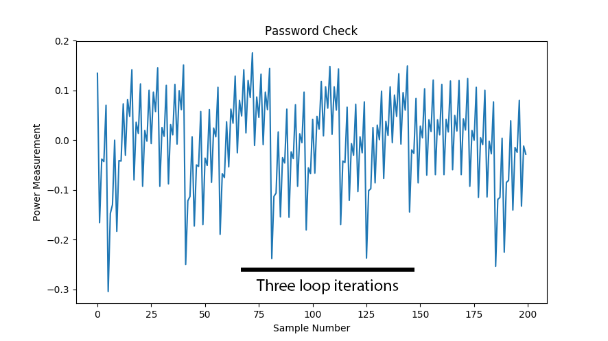
Such an attack could be performed from the communications protocol. But many systems will add a random delay before returning the results. With power analysis we could see the unique signatures in the power trace, as in Figure 1. Fig. 1. A simple password check shows how many iterations through the loop we took.
Figure 1: Loop Iterations in the Power Trace
These power measurement examples are taken with the ChipWhisperer project. Here the power measurements are done by inserting a shunt resistor into the device power pin, and using the fact that a change in current will cause a change in voltage across the resistor. The decoupling capacitors are removed in this example to provide a clean signal. This is shown in Figure 2.
Are you interested in this area of research? If you’ve followed some of my work you know I enjoy a combination of fundamental research & hands-on practical experiences.
It led me to co-found NewAE Technology Inc out of my PhD, with the objective of taking some of the research I was doing and pushing it ever further out into the world. I’m going to be continuing that work as C.T.O., but at the same time taking a leap forward in building up a larger research group under an academic affiliation.
I’ve joined Dalhousie University as an assistant professor in the electrical & computer engineering department. This is a bit of a unique position as I’m also going to be helping with some of the new innovation work being done in the “IDEA Building”, which means I’ll be mandated (and thus have time) to work with companies interested in cyber-security (emphasizing the sort of cyberphysical work I do, like IoT and automotive).
I’ll be shortly looking for students as well – if you are interested in a MASc or PhD in this area, I’d love to hear from you! Get in touch with my Dalhousie email (COFLYNN – AT – DAL.CA), if you don’t hear back sometimes I’m travelling quite a bit so may be slow, so please follow up to make sure I didn’t drop it. Or say hello at a conference – I’ll be at RECON and Black Hat in the next few months.
More details & update on this to come, but it’s an exciting chance for me to continue pushing the fundamental research I love, while engaging the local start-up community and helping encourage students that starting a business out of research isn’t such a bad idea.
Just a quick post to have someone with the text. In case you aren’t aware, Nova Scotia’s “Freedom of Information and Protection of Privacy” (FOIPOP) system allows you to request various information from the government, including information about yourself. When you request information about yourself it’s not redacted (i.e., your SIN and other information they have would be in the document), but when you request it about someone/something else information is redacted to protect their privacy.
They were serving these documents using a system with URLs like “https://foipop.novascotia.ca/foia/views/_AttachmentDownload.jsp?attachmentRSN=1234”, where the last number was the document. Which is fine until they decided to use this for both the sensitive and non-sensitive one, with no log-in or password checks. To a point, these documents were automatically indexed by Google and other services, as they didn’t even put a ROBOTS.txt is seems.
While somebody downloaded documents they “weren’t supposed to”, and they are now claiming he is a hacker. Note most of the documents accessed were public, and there was no way to tell them apart based on URL (so it’s not even an attempt at hacking). The following is my open letter to the province regarding this silliness:
April 17, 2018
The Honourable Stephen McNeil, Premier of Nova Scotia
Re: Nova Scotia handling of FOIPOP information leak
I’m writing to you with considerable alarm regarding the response to the exposure of confidential information via the FOIPOP portal. In particular, I am greatly alarmed by the handling of an individual accessing a public government website.
It is clear the document storage and display system was designed for public documents only, as no attempt was made to authorize or validate the user. I can only assume this was a miscommunication about the intended use of this particular document storage system, as many of the documents appear on Google and other archives. Notably, even the most basic web configurations have a list of non-public directories which search engines such as Google will not access out of courtesy. There is no authentication or lock on these pages either, but the fact that no attempt was made to prevent such access clearly points to this being a publicly accessible document repository.
Attempts to claim this was somehow a “hack” or even “vulnerability exploitation” do not pass muster. Neither do explanations make sense that this is a case of someone stealing an unlocked bicycle, and thus they have still done something wrong. Rather this is a case of someone (hint – not the person that had their house stormed) leaving sensitive documents in the library stacks, and someone else finding them while looking through the books. They were placed in a public location without any access control – the “attacker” simply picked them up from this public space. In fact, in this case the sensitive documents even had the same labeling and numbering system as the public books on the shelf. They are completely indistinguishable until you look at the contents.
Despite this, the person finding the documents is being aggressively handled, and a story being created that is attempting to spin them into the antagonist. Heavy-handed attempts at pursuing “computer crime” have been widely recognized as being counter-productive of achieving a more productive and secure society – even when some actual crime may have occurred (which in itself appears questionable for the case at hand).
On one hand, the government is claiming they want to encourage investment and growth of technology in Nova Scotia. Cyber-security in particular has been recognized as a particular growth area of importance to Canada, with the latest federal budget spending $1 billion on cybersecurity. But the handling of this case sends a crystal-clear message to potential researchers and entrepreneurs that Nova Scotia is not somewhere you want to be, as they are still working under long disproven and outdated cyber-security enforcement tactics.
I do not believe the current outcome was malicious, but the result of many levels of confusion, miscommunication, and attempts to divert blame. Ultimately this miscommunication resulted in Halifax Regional Police conducting a raid under the pretense that a computer crime occurred.
There is still some hope of salvaging Nova Scotia’s reputation and future ability to attract critical cyber-security talent from across Canada and the world. This would require a frank admission of the failures within the government (this does not require scapegoating any specific employee), while also outlining remediation steps to provide justice for the “hacker”, and a plan to prevent such heavy-handed reactions from occurring in the future (such as some level of expert validation of computer crime complaints). Regaining public trust regarding handling of sensitive data involves additional work, but I believe the first three items outlined are the most time-critical for the matter at hand.
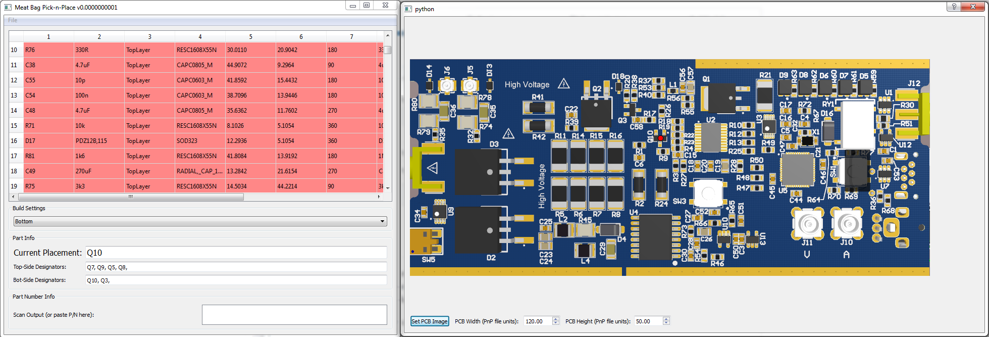
Have you ever hand-built a PCB prototype with lots of parts? If so you’ll know the annoyance of hand-building something from a big stack of Digi-Key parts. Having to Ctrl-F the part value in the design, and dealing with hits on both top & bottom side. Instead I’m introducing Meat-Bag Pick-n-Place, which helps you the human meatbag become a PnP machine! Here’s a photo of it running:
You can either click on an item, and it finds the first hit of it (i.e., click on a 200-ohm resistor) and shows you. You can then use spacebar to move through the placement list. It also interfaces to barcode scanners so you can just scan Mouser or Digikey bags. Here’s a short video demo: