Glitching Trezor using EMFI Through The Enclosure

As mentioned on the Trezor blog post, their latest security patch fixes a flaw I disclosed to them in Jan 2019. This flaw meant an attacker with physical access to the wallet can find the recovery seed stored in FLASH, and leave no evidence of tampering.

This work was heavily inspired by the wallet.fail disclosure – I’m directly dumping FLASH instead of forcing the flash erase then dumping from SRAM, so the results are the same but with a different path. It also has the same limitations – if you used a password protected recovery seed you can’t dump that.

Practically, it has the advantage of not requiring you to modify/tamper with the enclosure at all either to do the fault injection or read data off . Wallet.fail uses the physical JTAG connection, whereas I’m using the USB connection. But by comparison the wallet.fail attack is more robust and easier to apply – my EMFI attack can be fiddly to setup, and there is some inherent timing jitter due to the USB stack processing. Without further effort to speed up my attack, it’s likely the process of opening the enclosure & applying the wallet.fail method would be a faster in practice.

Please do not contact me if you have a “forgotten password” or something similar with your Trezor. I’m not willing to perform this work under any circumstances.

Summary

USB requests that read from memory (such as a USB descriptor read) accept a maximum packet size that is MIN(requested_size, size_of_data_structure). The code as written defaults to accepting the requested size, and overwriting it with a smaller “valid” value.

Using fault injection (here demo’d with EMFI), this check can be skipped. The device will accept up to 0xFFFF as a size argument, giving an attacker access to read large chunks of either SRAM or FLASH (depending where the descriptor is stored).

Due to the FLASH memory layout, the sensitive metadata lies roughly AFTER the descriptors stored in bootloader flash space. Thus an attacker can read out the metadata structure from memory (seed etc). Notably this does not require one to open the enclosure due to use of EMFI.

Using voltage glitching would almost certainly work as well, but likely requires opening the enclosure making tampering more evident (possibly it would work via USB +5V input even which wouldn’t require opening the enclosure).

Details

I’ve chosen to demo this with WinUSB descriptor requests, as they have a very simple structure. In addition the WinUSB has one descriptor in FLASH and one in SRAM, giving you the ability to chose which memory segment to dump. Other USB requests should work too, but I haven’t tested them.

Consider the following function, where the critical calls are the len = MIN(len,…) calls (two of them can be found):

static int winusb_control_vendor_request(usbd_device *usbd_dev,
					struct usb_setup_data *req,
					uint8_t **buf, uint16_t *len,
					usbd_control_complete_callback* complete) {
	(void)complete;
	(void)usbd_dev;

	if (req->bRequest != WINUSB_MS_VENDOR_CODE) {
		return USBD_REQ_NEXT_CALLBACK;
	}

	int status = USBD_REQ_NOTSUPP;
	if (((req->bmRequestType & USB_REQ_TYPE_RECIPIENT) == USB_REQ_TYPE_DEVICE) &&
		(req->wIndex == WINUSB_REQ_GET_COMPATIBLE_ID_FEATURE_DESCRIPTOR)) {
		*buf = (uint8_t*)(&winusb_wcid);
		*len = MIN(*len, winusb_wcid.header.dwLength);
		status = USBD_REQ_HANDLED;

	} else if (((req->bmRequestType & USB_REQ_TYPE_RECIPIENT) == USB_REQ_TYPE_INTERFACE) &&
		(req->wIndex == WINUSB_REQ_GET_EXTENDED_PROPERTIES_OS_FEATURE_DESCRIPTOR) &&
		(usb_descriptor_index(req->wValue) == winusb_wcid.functions[0].bInterfaceNumber)) {

		*buf = (uint8_t*)(&guid);
		*len = MIN(*len, guid.header.dwLength);
		status = USBD_REQ_HANDLED;

	} else {
		status = USBD_REQ_NOTSUPP;
	}

	return status;
} 

We can see from disassembly this is a simple comparison to the maximum size. I’m mostly going to be looking at the guid structure since it’s located in FLASH below the metadata. Glitching the code in the red box below would create our required vulnerability:

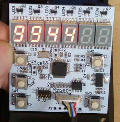
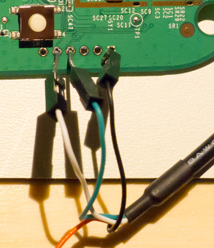
The glitch is inserted with a ChipSHOUTER EMFI tool. The Trezor is held in bootloader mode with two spacers on the buttons, and the EMFI tool is positioned above the case, as shown below:

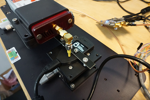
The entire setup is shown below, which has the ChipSHOUTER (bottom left), a ChipWhisperer-Lite (top left) for trigger delay, a Beagle 480 for USB sniffing/triggering (top center) and a switchable USB hub to power-cycle the Trezor when the EMFI triggers the various hard fault/stack smashing/memory corruption errors (top right).

The forced bootloader entry mode simplifies the glitch, as we can freely power cycle the device and try many glitches.

A glitch is timed based on a Total Phase USB analyzer. The USB request is sent from a host computer as shown below:

def get_winusb(dev, scope):
    """WinUSB Request is most useful for glitch attack"""  
    scope.io.glitch_lp = True #Enable glitch (actual trigger comes from Total Phase USB Analyzer)
    scope.arm()    
    resp = dev.ctrl_transfer(int('11000001', 2), ord('!'), 0x0, 0x05, 0xFFFF, timeout=1)
    resp = list(resp)    
    scope.io.glitch_lp = False #Disable glitch
    return resp

This corresponds to reading the “guid”. The Beagle480 is setup to generate a trigger on the first two bytes of this request:

To confirm the timing, I also compiled my own bootloader, and saw the sensitive operation was typically occurring in the 4.2 to 5.7uS after the Beagle480 trigger. There was some jitter due to the USB stack processing.

A ChipWhisperer-Lite is used to then generate a 4.4uS offset (empirically a good “waiting” place), after which an EMFI pulse is triggered. Should the 4.4uS offset happen to line up with the length checking/limiting, we can get a successful glitch.

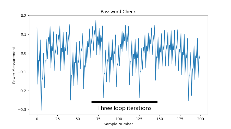
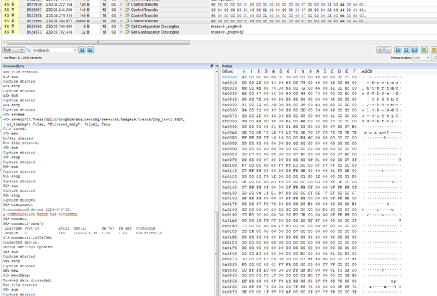
A successful glitch will return much more data than expected – possibly up to the full 0xFFFF, but because things are getting corrupted it sometimes seems to be less. Also some OSes limited the maximum size you can request -you can find some references to that on the libusb mailing list. As a first step you might just try 0x1FF or something (anything larger than the correct 0x92 response). But here is a screen-shot showing three correct transfers (146 bytes transferred) followed by an incorrect one, which dumped 24800 bytes:

Here is an example metadata from another dump (this doesn’t correspond to the screen-shot above), note I never set a PIN as I had damaged the screen since the first device I tested with was being used for development as well:


Simulating the Glitch

Note you can “simulate” this glitch by simply commenting out the length checking operation in the WinUSB request. This allows you to confirm that should that operation be skipped, you can dump large chunks of memory including the metadata.

This simulation could be useful in validating some of the proposed fixes as well (I would highly suggest doing such testing as part of regular building).

Reliability Notes

Note due to the timing jitter the glitch is very unreliable (<0.1% success rate), however this typically translates to taking a few hours due to how quickly the search can be done. So it remains extremely practical since it seems reasonable for an attacker to have access to a wallet for a few hours.

I suspect this could be improved by doing the USB request from an embedded system (something like a GreatFET), which would allow me to synchronize a device to the internal state of the Trezor. This would mean the operation would be:

  1. Send a USB request (get descriptor etc).
  2. After the USB request comes back, send our WinUSB/glitch target request at a very defined amount of time after we received the USB request.
  3. Insert the glitch.

Simple Fixes / Countermeasures

1) The low-level USB functions should accept some absolute maximum size. For example, if you only ever do 64-byte transfers, never allow a larger transfer to occur by masking upper bits to force them to zero. Do this in multiple spots to make glitching past this more difficult.

2) The metadata needs to be guarded by invalid memory segments. Doing a read from a valid segment to the metadata should hit an invalid segment, causing an exception.

3) Move descriptor /metadata arrangement (less useful than #2 in practice).

Conclusions

EMFI is a simple way of abusing the USB stack in the Trezor. You’ll find a similar vulnerability in a number of USB stacks, meaning this type of attack should be something you validate against in your own devices.

More details of this example will be available in the book Jasper & I are working on for (eventual?) release.

Embedded World 2019 Conference Talk

At Embedded World I gave a talk on embedded security. There was also an associated paper, and I’m now making those available. I’ve also duplicated the paper contents in this blog post for your ease of access.

Download Slides (PPTX):

Click the above to download PPTX


ABSTRACT: As interconnected devices proliferate, security of those devices becomes more important. Two critical attacks can bypass many standard security mechanisms. These attacks are broadly known as side-channel attacks & fault injection attacks. This paper will introduce side-channel power analysis and fault injection attacks and their relevance to embedded systems. Examples of attacks are given, along with a short discussion of countermeasures and effectiveness. The use of open-source tools is highlighted, allowing the reader the chance to better understand these attacks with hands-on examples.

Introduction

Side-channel attacks are the broad class given to attacks which rely on “additional information” that is accidentally leaked. A variety of such side-channels exist, such as the time an algorithm takes to execute can betray information about the code paths taken in the algorithm. Of great interest to embedded developers is side channel power analysis, first introduced by Kocher et al. in 1999 [1]. This attack takes advantage of a small piece of information – the data being processed by a system affects the power consumption of that system. This allows us to break advanced cryptography systems such as recovering an AES-256 key in a matter of minutes. These attacks do not rely on substantial resources – they can be performed with commodity hardware and for less than $50. A second class of attack will be known as fault injection attacks. They allow us to modify the program flow of code, which can cause a variety of security flaws to be exploited. This paper will briefly introduce those two methods of attacks and discuss how engineers can understand them to develop effective countermeasures.

Power Analysis for Algorithm Flow

The most basic form of power analysis attack is simple power analysis. In this method we will extract information about the algorithm flow. This could be used to directly extract key bits where changes in program flows reveal key information (such as with RSA), but can also be used to extract information such as timing that simplifies further attacks. Observe a simple password check which checks a byte of the password at a time. The execution time through this algorithm would reveal which password byte was incorrect, allowing an attacker the ability to quickly brute-force the algorithm. A password of ADBC would entail only the guess sequence “A/A..B..C..D/A..B../A..B…C” to find the correct password, as once the correct letter is found for one digit the guess algorithm can move onto the next digit.

Such an attack could be performed from the communications protocol. But many systems will add a random delay before returning the results. With power analysis we could see the unique signatures in the power trace, as in Figure 1. Fig. 1. A simple password check shows how many iterations through the loop we took.

Figure 1: Loop Iterations in the Power Trace

These power measurement examples are taken with the ChipWhisperer project. Here the power measurements are done by inserting a shunt resistor into the device power pin, and using the fact that a change in current will cause a change in voltage across the resistor. The decoupling capacitors are removed in this example to provide a clean signal. This is shown in Figure 2.

Continue reading Embedded World 2019 Conference Talk

More Research, More Fun – I’m now an Assistant Professor

Are you interested in this area of research? If you’ve followed some of my work you know I enjoy a combination of fundamental research & hands-on practical experiences.

It led me to co-found NewAE Technology Inc out of my PhD, with the objective of taking some of the research I was doing and pushing it ever further out into the world. I’m going to be continuing that work as C.T.O., but at the same time taking a leap forward in building up a larger research group under an academic affiliation.

I’ve joined Dalhousie University as an assistant professor in the electrical & computer engineering department. This is a bit of a unique position as I’m also going to be helping with some of the new innovation work being done in the “IDEA Building”, which means I’ll be mandated (and thus have time) to work with companies interested in cyber-security (emphasizing the sort of cyberphysical work I do, like IoT and automotive).

I’ll be shortly looking for students as well – if you are interested in a MASc or PhD in this area, I’d love to hear from you! Get in touch with my Dalhousie email (COFLYNN – AT – DAL.CA), if you don’t hear back sometimes I’m travelling quite a bit so may be slow, so please follow up to make sure I didn’t drop it. Or say hello at a conference – I’ll be at RECON and Black Hat in the next few months.

More details & update on this to come, but it’s an exciting chance for me to continue pushing the fundamental research I love, while engaging the local start-up community and helping encourage students that starting a business out of research isn’t such a bad idea.

Breaking Electronic Door Locks Like You’re on CSI: Cyber – Black Hat 2017 Talk

This year at Black Hat I’m presenting some short work on breaking electronic door locks. This talk focuses on one particular residential door lock. There was a bit of a flaw in the design, where the front panel/keypad can be removed from the outside.

Once the keypad is off, you have access to a connector that goes into the rear side of the device. You can then make a cool “brute force” board, which was basically the point of this presentation. Finally you can have something that looks like your movie electronic lock hacking mechanism, completed with 7-segment LED displays:

This little device does the following:

  • Emulates the front-panel keyboard.
  • Sends a number of guesses into the lock in quick succession.
  • Resets the backend lock to bypass the timeout mechanism when too many wrong guesses are put in.

The last part of the attack is the one that makes this a “vaguely useful” attack. The reset process is a little slow, but fast enough you could brute-force the 4-digit code in about 85 mins.

If you wanted to replace the external keyboard (so the owner didn’t know you were playing with it), it’s potentially possible but it requires very good conditions at best (i.e., good lighting, good angle, proper tools). For my demos I’ve added some restraints around the connector to make it more stationary such I can replace the keyboard without these tools.

As you can image, any “real” attacker is likely to use existing entry methods (bypass door, drill lock, kick down etc) instead of this slow/exotic attack. Despite this low risk the vendor is working on a fix. It sounds to be a VERY robust fix too, this isn’t a small change to stop only my specific board/attack either.

Hopefully this talk helps show various design teams about where people might be probing their products. Sometimes it’s just a little change in perspective is all it takes. Design engineers are often in the mindset of “design within given parameters”, but attackers are going to be looking outside of those design specs for weaknesses. Once you give the design engineer the perspective of considering the front-panel removable & a hostile environment for example, they may come up with all sorts of other attacks I didn’t think of (and thus will improve the products to prevent this).

Ultimately I think it will help consumers win, since they can be more confident that important products (such as these electronic locks) are at least as strong as an old mechanical lock.

PhD Thesis Finally Done

If you’ve seen my presentations anytime over the past few years, you’ll know the introduction about “PhD Student at Dalhousie University finishing ‘soon'” has been the claim for the past several years. Finally ‘soon’ actually happened!

You can see my complete thesis entitled “A Framework for Embedded Hardware Security Analysis” on the DalSpace website. It’s been a ton of fun doing the PhD, and I’ve had a lot of help over the years which I’ve very grateful for. For the foreseeable future I’ll be continuing to spin up NewAE Technology Inc., and keeping my ChipWhisperer project alive.

Philips Hue, AES-CCM, and more!

This is just a quick blog post to update you on some rather interesting research that will be coming out led by Eyal Ronen. At Black Hat USA 2016 I did some teardown of the Philips Hue system, and described the possibility of a lightbulb worm.

Check this landing page which now has a draft PDF of what that became. This draft paper details how you can (1) recover the encryption keys used to encrypt the firmware updates, and thus encrypt/sign your own images, and (2) details a bug specific to a version of a range-checking protocol which allows reflashing of bulbs over longer distances. The end result is this basically solves all the roadblocks I had identified as stopping the lighbulb worm from actually happening [NB: the distance-check bug has been FIXED already in firmware updates which solves this specific spreading vector].

To me the most interesting part is a demonstration of side-channel power analysis being useful for breaking a rather good encrypted bootloader. To be clear the Philips Hue does a great job of implementing a bootloader on an IoT device… it’s one of the better I’ve seen, especially considering we are talking about a lightbulb. But it’s very very difficult to hide from side-channel power analysis and other “hands on” embedded hardware attacks, instead it’s better (but more expensive logistically) to push the solutions to the higher-level architecture. If each bulb had a unique encryption key (maybe derived from the MAC address using an algorithm on a secure server if you don’t want to store all those keys) it would provide an excellent layer of defense.

I’m working on making a description of the AES-CCM attack, which will be posted to the wiki page.


Q: What does that mean to someone using Hue, is it safe?

A: Philips released a OTA update to fix the bug that allows spreading over longer distances (October 3rd update). This is a great example of a fast response by a company who takes this stuff seriously. Basically – if I was choosing a smart light platform, I’d probably use Hue (I have a few of them in my house too).


Q: What’s power analysis?

A: This isn’t a FAQ type answer – but you can see an intro video I made. Basically we use tiny variations in power consumption of a device as it’s running to determine information about secrets held within the device.


Q: What if I want more information?

A: Please contact Eyal for more details, if you want to discuss specific questions, etc. Note the Philips-specific details (such as scripts, keys, etc) will never be released, please don’t ask for them.


Q: Does a worm exist?

A: NO. It would be extremely reckless to make such a worm, as it would be VERY hard to contain the spread should you have a bunch of Hue devices around you. Instead that research paper demo’d all the pieces, but stopped short of putting them together (we wouldn’t want a criticality accident).

Philips Hue – R.E. Whitepaper from Black Hat 2016

At Black Hat 2016 I presented on some reverse engineering of the Philips Hue (also see my other post about getting root on it, which was part of that presentation).

If you were at the talk, you would have also seen mention that you’ll want to keep your eyes out for future publications by Eyal Ronen. You can see his website for more research related to the Hue as well, and follow him on twitter @eyalr0. He’s been doing some work in parallel that I think will do more than just R.E. the bulbs (as I did), and actually bring some of my `possible’ attacks to become real proof-of-concepts.

Summary of the work (to make it clear):

  • I did NOT make a worm. The title was a question someone asked me, and the talk is about the security of the Hue.
  • The mention of a possible ‘Long Range Take Over’ was new/unreleased research by Eyal Ronen – do not credit me with that. It’s part of a larger research publication that will get released at some point.
  • Philips did a rather good job (all things considered). The only trade-off I really call out is reuse of encryption keys across all FW updates for all devices, which is basically what makes a theoretical worm possible.
  • Rooting the Hue (earlier post) is a local attack and very nice for hardware hackers. There are unique root passwords which is a great security step, so far I haven’t found flaws in the Hue Bridge 2.0 besides that.
  • There’s a lot of “interesting vectors” which the talk goes over. Given enough time some of them may give, but it’s a question of who is motivated enough to spend a lot of time on them.

You can get the full slides here too:

Philips Hue Reverse Engineering (BH Talk ‘A Lightbulb Worm?’) Slides [PDF, 8MB]

Here’s a copy of the very large whitepaper I wrote too:

Philips Hue Reverse Engineering (BH Talk ‘A Lightbulb Worm?’) Whitepaper [PDF, 5MB]

This whitepaper is a bit of a ‘data dump’ and ~48 pages of random stuff. But useful if you are interested in pushing this further!

Black Hat Slides – PIN-Protected HD Enclosure / MB86C311A Research

This is a quick post to link to slides from my Black Hat USA 2016 work.

This work stands directly on the work done by Joffrey Czarny & Raphaël Rigo presented at HardWear.io last year (2015). They discovered the issues w.r.t. the stream-mode cipher being used by all manufactures on the MB86C311A, and the fact that secrets are stored on the HD itself. Their work is available at:

They have some newer work coming out which looks to be very interesting, so please keep your eyes out for that. Anyway onto my stuff. The following is a link to my slides:

Brute-Forcing Lockdown Harddrive PIN Codes [Slides]


Getting Root on Philips Hue Bridge 2.0

This post will briefly show you how to get a root console on the new Philips Hue Bridges (the square ones). It’s rather easy, the only special tools you require are a USB-Serial cable & a torx screwdriver.

P1080978

There’s a video with full details, this post is just the specifics if you don’t want a very boring walk-through:

  1. For the serial cable (a standard 3.3V type one, DO NOT use a 5V cable), there is a 6-pin header along the bottom. Pin ‘1’ has a square footprint, and counting from pin 1 the connections are:
    Pin 1 = GND
    Pin 4 = RX In (connect to TX Out of your serial cable)
    Pin 5 = TX Out (connect to RX in of your serial cable).

    P1080980

  2. The bottom left-corner of the 2-row header is GND. You’ll have to short that with a wire to the following test point:

    P1080981
    This test-point is shorted to GND with a paper-clip or wire. Click image for full-sized to see in better detail.
  3. To get the system working, check you are getting boot messages. Now, restart the system and after you get a bit of output, short the pin. You might see some output like this:
    U-Boot 1.1.4 (Sep  8 2015 - 04:08:21)
    
    bsb002 - Honey Bee 2.0DRAM:  
    sri
    Honey Bee 2.0
    ath_ddr_initial_config(195): (16bit) ddr2 init
    tap = 0x00000003
    Tap (low, high) = (0x8, 0x22)
    Tap values = (0x15, 0x15, 0x15, 0x15)
    64 MB
    Top of RAM usable for U-Boot at: 84000000
    Reserving 214k for U-Boot at: 83fc8000
    Reserving 192k for malloc() at: 83f98000
    Reserving 44 Bytes for Board Info at: 83f97fd4
    Reserving 36 Bytes for Global Data at: 83f97fb0
    Reserving 128k for boot params() at: 83f77fb0
    Stack Pointer at: 83f77f98
    Now running in RAM - U-Boot at: 83fc8000
    Flash Manuf Id 0xc8, DeviceId0 0x40, DeviceId1 0x13
    flash size 0MB, sector count = 8
    Flash: 512 kB
    *** Warning *** : PCIe WLAN Module not found !!!
    In:    serial
    Out:   serial
    Err:   serial
    Net:   ath_gmac_enet_initialize...
    Fetching MAC Address from 0x83febe80
    Fetching MAC Address from 0x83febe80
    ath_gmac_enet_initialize: reset mask:c02200 
    Scorpion ---->S27 PHY*
    S27 reg init
    : cfg1 0x800c0000 cfg2 0x7114
    eth0: 00:03:7f:11:20:ce
    athrs27_phy_setup ATHR_PHY_CONTROL 4 :1000
    athrs27_phy_setup ATHR_PHY_SPEC_STAUS 4 :10

    Which will then fall back to a prompt:

    ath>

    Good news! We can now get everything working for you. You can print the existing variables if you wish:

    ath> printenv
  4. Set a boot delay such we can enter the menu without the boot hack:
    setenv bootdelay 3

    Check it works with

    printenv bootdelay

    and confirm you get a line like this:

    bootdelay=3

    Finally, save the setting with:

    saveenv

    You can now reset the system (use the ‘reset’ command), and confirm there is a count-down that gives you time to hit “enter” and get this prompt again.

  5. Now let’s fix the root password. Before doing this, I suggest you keep a copy of the old value:
    printenv security

    This would let you restore things back to default. Then the following will set the root password to ‘toor’:

    setenv security '$1$3vGNd7Q3$ISqFeo1VkmQV6nyriUV0V/'

    You may have to copy this into notepad first to ensure it all fits on one line! The quotes are critical here. Again check it works with printenv, then type saveenv to store things to disk.

    If you want your own password, simply use the ‘mkpasswd’ command in Linux to generate an appropriate string.

    NOTE: My original instructions (and the video) had a different ‘setenv’ command, which used SHA1 to hash the password. It turns out this stops ssh from working, so instead as suggested in the comments you can use the above MD5 hash which should work better. For posterity my original instructions were:

    setenv security '$5$wbgtEC1iF$ugIfQUoE7SNg4mplDI/7xdfLC7jXoMAkupeMsm10hY9'
  6. Once again reset the board – assuming you used saveenv, that root password will be used by the system now. You should be able to log in with root/toor!
  7. Once you are in, there’s a few changes you’ll want to make. We’ll edit the file /etc/rc.local:
    # vi /etc/rc.local

    And add the following:

    iptables -I INPUT -p tcp --dport 23 --syn -j ACCEPT
    telnetd

    This will open the telnet port & start the daemon on boot. Write the file and quit with :wq. You may also want to add the /etc/rc.local to the /etc/sysupgrade.conf file to avoid it being overwritten in the future.

    See the comments below – someone found a way to get ‘dropbear’ to allow root login too. It’s great as SSH is much nicer to work with than telnet! This requires a different password hash than my original instructions/video.

  8. Try using telnet to connect now. You can find the IP of the bridge using ifconfig, but you can also get it through the Hue app.You can also try using “Philips-hue.local”, which I’d first check via ping to see if it resolves:
    ping Philips-hue.local
  9. I’ve done the 25-July-2016 update without issue too (after first rooting the hub with an earlier version). I’ll continue to update this as updates happen.

BONUS – How did I figure this out?

The “bomb out to uboot prompt” is a known bug. Once in the prompt, I could edit the bootarg command with this:

setenv std_bootargs 'board=BSB002 console=ttyS0,115200 ubi.mtd=overlay rootfs=/dev/mtdblock:rootfs rootfstype=squashfs noinitrd init=/bin/sh';

This gives me a shell which doesn’t require a login. But many things are broken/disabled in this mode. It was however enough to find that there is another script that runs on startup which uses the uboot env variable, and copies it into the shadow file for the root password.

With this knowledge it’s easy to use mkpasswd to make an appropriate shadow file entry. Easy!

I also checked with two different Hue Bridge v2.0 devices. They contained different root passwords (at least different salts). I’ve been told the root passwords are indeed unique per device, which is a good step to stop someone from attacking your virgin Philips Hue 2.0 bridge.

As an interesting note – other people have also discovered this independently of me. Between writing this post & actually linking it from anywhere (i.e., so you could actually find it) pepe2k figured out the same thing on a forum post.

As well someone else did this same “overwrite root” attack already, but had used an external programmer to write the FLASH memory chip:

So it’s worth considering that many devices may be broken even if there isn’t some fancy Black Hat talk or otherwise. Most of the attacks (such as this one) are fairly well-known and pretty basic.

UPDATE: At DEFCON 24, I guess someone gave this type of attack a marketable name. You can see the idea called pin2pwn here.

SECT-2015 Talk Slides

On Friday at 14:15 I’m giving a talk about my open-source power analysis and glitching projected called ChipWhisperer at SEC-T. Here is some useful links if you watched the presentation:

See information about the entire project at www.ChipWhisperer.com too! Video will be posted online at some point too.